This post is older than 2 years and might not be relevant anymore
More Info: Consider searching for newer posts

Connect nRF DevKit (WSM-BL241-ADA-008DK) to Accelerometer (STEVAL-MKI197V1).

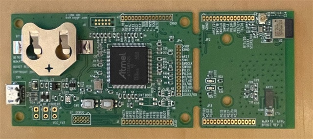
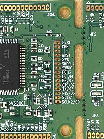
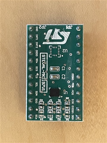
We want to physically connect our nRF muRata dk (WSM-BL241-ADA-008DK) to the ST Accelerometer eval board (STEVAL-MKI197V1). We are assuming the connection takes place on the JP4 pads but can't find a 3.3v power output pin and don't want to guess. The goal is to write firmware using nRF Connect and define interrupts on the nRF board for inbound Accelerometer changes. We want to test both spi and i2c

Any one have experience here? thank you!

Parents
  • Hello, 

    Have you looked at the documentation of the WSM-BL241-ADA-008DK, and the MBN52832DK module found on this board? As this is a Murata board, you will need to see their documentation on how they have routed GPIO, etc. 

    Kind regards,
    Øyvind

  • Hi -

    Thanks for the response! Yes, we've looked at the muRata board schematic and data-sheets. This is what we now know.

    NOTE: I realize that you may not know anything about the following. Just wanted to let you know we've been researching and are trying to ask intelligent questions to make our way forward.

    DONE: installed and successfully ran the SPI Master example found in the nRF sdk on the muRata. But the LMS accelerometer was not connected at the time.(https://infocenter.nordicsemi.com/topic/com.nordic.infocenter.sdk5.v12.0.0/spi_master_example.html). 

    The muRata board comes in two parts; Interface Module and Breakaway Module

    The mbn52832_schematic.pdf calls out PA13/MISO, PA14/MOSI on the IC but we can't seem to identify those connection points are on the the Interface Module. The Interface Module seems to provide USB-SWD and USB-UART for installing and debugging. However, the Breakaway Module does have a 2.8v power output.

    DONE:  Connected muRata Breakaway Module JP2 VDD and GRD to the lms6dsox accelerometer VDD and GRD. Can reliably get 2.75v on multimeter measured directly on the lms eval board pins. (And we didn't smell any smoke :)

    nRF SDK:
    The SPI struct (nrfx_spi_config_t) looks like it will take any general purpose gpio that's available for SLC, MISO, MOSI, CS. (Is this correct??)

    Proposed hook up if the muRata will allow for generic pin assignment - meaning we can assign SLC, MISO, MOSI, and CS to gpio pins on the muRata. The lms accelerometer pins are clearly marked.

     mbn52382 BreakAway JP2 Pads mbn52382 BreakAway JP3 pads LMS Accelerometer
    VDD VDD
    GRD GRD
    PO.15 SCL (clock)
    PO.16 SD0 (MISO)
    PO.17 SCL (MOSI)
    PO.30 SC (slave select)
  • Hello, 

    I do not have knowledge of the muRata board and its components, these will need to be directed to muRata directly. 

    For the nRF5 SDK and the nRF52832 I will try to give an answer that will help you using the breakaway module.

    briangraph said:
    The SPI struct (nrfx_spi_config_t) looks like it will take any general purpose gpio that's available for SLC, MISO, MOSI, CS. (Is this correct??)

     First of all, I see you are using an older version of nRF5 SDK. v12, is there a reason for this? Why not use a newer SDK i.e. nRF5 SDK v17?

    The pins of the SPI module is configured in sdk_config.h found under PCA10040 (nRF52832). 

    //==========================================================
    // <h> SPI_CONFIGURATION - Spi configuration
    
    //==========================================================
    // <o> SPI_SCK_PIN  - Pin number
     
    // <0=> 0 (P0.0) 
    // <1=> 1 (P0.1) 
    // <2=> 2 (P0.2) 
    // <3=> 3 (P0.3) 
    // <4=> 4 (P0.4) 
    // <5=> 5 (P0.5) 
    // <6=> 6 (P0.6) 
    // <7=> 7 (P0.7) 
    // <8=> 8 (P0.8) 
    // <9=> 9 (P0.9) 
    // <10=> 10 (P0.10) 
    // <11=> 11 (P0.11) 
    // <12=> 12 (P0.12) 
    // <13=> 13 (P0.13) 
    // <14=> 14 (P0.14) 
    // <15=> 15 (P0.15) 
    // <16=> 16 (P0.16) 
    // <17=> 17 (P0.17) 
    // <18=> 18 (P0.18) 
    // <19=> 19 (P0.19) 
    // <20=> 20 (P0.20) 
    // <21=> 21 (P0.21) 
    // <22=> 22 (P0.22) 
    // <23=> 23 (P0.23) 
    // <24=> 24 (P0.24) 
    // <25=> 25 (P0.25) 
    // <26=> 26 (P0.26) 
    // <27=> 27 (P0.27) 
    // <28=> 28 (P0.28) 
    // <29=> 29 (P0.29) 
    // <30=> 30 (P0.30) 
    // <31=> 31 (P0.31) 
    // <4294967295=> Not connected 
    
    #ifndef SPI_SCK_PIN
    #define SPI_SCK_PIN 26
    #endif
    
    // <o> SPI_MISO_PIN  - Pin number
     
    // <0=> 0 (P0.0) 
    // <1=> 1 (P0.1) 
    // <2=> 2 (P0.2) 
    // <3=> 3 (P0.3) 
    // <4=> 4 (P0.4) 
    // <5=> 5 (P0.5) 
    // <6=> 6 (P0.6) 
    // <7=> 7 (P0.7) 
    // <8=> 8 (P0.8) 
    // <9=> 9 (P0.9) 
    // <10=> 10 (P0.10) 
    // <11=> 11 (P0.11) 
    // <12=> 12 (P0.12) 
    // <13=> 13 (P0.13) 
    // <14=> 14 (P0.14) 
    // <15=> 15 (P0.15) 
    // <16=> 16 (P0.16) 
    // <17=> 17 (P0.17) 
    // <18=> 18 (P0.18) 
    // <19=> 19 (P0.19) 
    // <20=> 20 (P0.20) 
    // <21=> 21 (P0.21) 
    // <22=> 22 (P0.22) 
    // <23=> 23 (P0.23) 
    // <24=> 24 (P0.24) 
    // <25=> 25 (P0.25) 
    // <26=> 26 (P0.26) 
    // <27=> 27 (P0.27) 
    // <28=> 28 (P0.28) 
    // <29=> 29 (P0.29) 
    // <30=> 30 (P0.30) 
    // <31=> 31 (P0.31) 
    // <4294967295=> Not connected 
    
    #ifndef SPI_MISO_PIN
    #define SPI_MISO_PIN 30
    #endif
    
    // <o> SPI_MOSI_PIN  - Pin number
     
    // <0=> 0 (P0.0) 
    // <1=> 1 (P0.1) 
    // <2=> 2 (P0.2) 
    // <3=> 3 (P0.3) 
    // <4=> 4 (P0.4) 
    // <5=> 5 (P0.5) 
    // <6=> 6 (P0.6) 
    // <7=> 7 (P0.7) 
    // <8=> 8 (P0.8) 
    // <9=> 9 (P0.9) 
    // <10=> 10 (P0.10) 
    // <11=> 11 (P0.11) 
    // <12=> 12 (P0.12) 
    // <13=> 13 (P0.13) 
    // <14=> 14 (P0.14) 
    // <15=> 15 (P0.15) 
    // <16=> 16 (P0.16) 
    // <17=> 17 (P0.17) 
    // <18=> 18 (P0.18) 
    // <19=> 19 (P0.19) 
    // <20=> 20 (P0.20) 
    // <21=> 21 (P0.21) 
    // <22=> 22 (P0.22) 
    // <23=> 23 (P0.23) 
    // <24=> 24 (P0.24) 
    // <25=> 25 (P0.25) 
    // <26=> 26 (P0.26) 
    // <27=> 27 (P0.27) 
    // <28=> 28 (P0.28) 
    // <29=> 29 (P0.29) 
    // <30=> 30 (P0.30) 
    // <31=> 31 (P0.31) 
    // <4294967295=> Not connected 
    
    #ifndef SPI_MOSI_PIN
    #define SPI_MOSI_PIN 29
    #endif
    
    // <o> SPI_SS_PIN  - Pin number
     
    // <0=> 0 (P0.0) 
    // <1=> 1 (P0.1) 
    // <2=> 2 (P0.2) 
    // <3=> 3 (P0.3) 
    // <4=> 4 (P0.4) 
    // <5=> 5 (P0.5) 
    // <6=> 6 (P0.6) 
    // <7=> 7 (P0.7) 
    // <8=> 8 (P0.8) 
    // <9=> 9 (P0.9) 
    // <10=> 10 (P0.10) 
    // <11=> 11 (P0.11) 
    // <12=> 12 (P0.12) 
    // <13=> 13 (P0.13) 
    // <14=> 14 (P0.14) 
    // <15=> 15 (P0.15) 
    // <16=> 16 (P0.16) 
    // <17=> 17 (P0.17) 
    // <18=> 18 (P0.18) 
    // <19=> 19 (P0.19) 
    // <20=> 20 (P0.20) 
    // <21=> 21 (P0.21) 
    // <22=> 22 (P0.22) 
    // <23=> 23 (P0.23) 
    // <24=> 24 (P0.24) 
    // <25=> 25 (P0.25) 
    // <26=> 26 (P0.26) 
    // <27=> 27 (P0.27) 
    // <28=> 28 (P0.28) 
    // <29=> 29 (P0.29) 
    // <30=> 30 (P0.30) 
    // <31=> 31 (P0.31) 
    // <4294967295=> Not connected 
    
    #ifndef SPI_SS_PIN
    #define SPI_SS_PIN 31
    #endif

    Here you can configure the pins of JP3 P0.15, P0.16, P0.17 and P0.30. 

    Kind regards,
    Øyvind

Reply
  • Hello, 

    I do not have knowledge of the muRata board and its components, these will need to be directed to muRata directly. 

    For the nRF5 SDK and the nRF52832 I will try to give an answer that will help you using the breakaway module.

    briangraph said:
    The SPI struct (nrfx_spi_config_t) looks like it will take any general purpose gpio that's available for SLC, MISO, MOSI, CS. (Is this correct??)

     First of all, I see you are using an older version of nRF5 SDK. v12, is there a reason for this? Why not use a newer SDK i.e. nRF5 SDK v17?

    The pins of the SPI module is configured in sdk_config.h found under PCA10040 (nRF52832). 

    //==========================================================
    // <h> SPI_CONFIGURATION - Spi configuration
    
    //==========================================================
    // <o> SPI_SCK_PIN  - Pin number
     
    // <0=> 0 (P0.0) 
    // <1=> 1 (P0.1) 
    // <2=> 2 (P0.2) 
    // <3=> 3 (P0.3) 
    // <4=> 4 (P0.4) 
    // <5=> 5 (P0.5) 
    // <6=> 6 (P0.6) 
    // <7=> 7 (P0.7) 
    // <8=> 8 (P0.8) 
    // <9=> 9 (P0.9) 
    // <10=> 10 (P0.10) 
    // <11=> 11 (P0.11) 
    // <12=> 12 (P0.12) 
    // <13=> 13 (P0.13) 
    // <14=> 14 (P0.14) 
    // <15=> 15 (P0.15) 
    // <16=> 16 (P0.16) 
    // <17=> 17 (P0.17) 
    // <18=> 18 (P0.18) 
    // <19=> 19 (P0.19) 
    // <20=> 20 (P0.20) 
    // <21=> 21 (P0.21) 
    // <22=> 22 (P0.22) 
    // <23=> 23 (P0.23) 
    // <24=> 24 (P0.24) 
    // <25=> 25 (P0.25) 
    // <26=> 26 (P0.26) 
    // <27=> 27 (P0.27) 
    // <28=> 28 (P0.28) 
    // <29=> 29 (P0.29) 
    // <30=> 30 (P0.30) 
    // <31=> 31 (P0.31) 
    // <4294967295=> Not connected 
    
    #ifndef SPI_SCK_PIN
    #define SPI_SCK_PIN 26
    #endif
    
    // <o> SPI_MISO_PIN  - Pin number
     
    // <0=> 0 (P0.0) 
    // <1=> 1 (P0.1) 
    // <2=> 2 (P0.2) 
    // <3=> 3 (P0.3) 
    // <4=> 4 (P0.4) 
    // <5=> 5 (P0.5) 
    // <6=> 6 (P0.6) 
    // <7=> 7 (P0.7) 
    // <8=> 8 (P0.8) 
    // <9=> 9 (P0.9) 
    // <10=> 10 (P0.10) 
    // <11=> 11 (P0.11) 
    // <12=> 12 (P0.12) 
    // <13=> 13 (P0.13) 
    // <14=> 14 (P0.14) 
    // <15=> 15 (P0.15) 
    // <16=> 16 (P0.16) 
    // <17=> 17 (P0.17) 
    // <18=> 18 (P0.18) 
    // <19=> 19 (P0.19) 
    // <20=> 20 (P0.20) 
    // <21=> 21 (P0.21) 
    // <22=> 22 (P0.22) 
    // <23=> 23 (P0.23) 
    // <24=> 24 (P0.24) 
    // <25=> 25 (P0.25) 
    // <26=> 26 (P0.26) 
    // <27=> 27 (P0.27) 
    // <28=> 28 (P0.28) 
    // <29=> 29 (P0.29) 
    // <30=> 30 (P0.30) 
    // <31=> 31 (P0.31) 
    // <4294967295=> Not connected 
    
    #ifndef SPI_MISO_PIN
    #define SPI_MISO_PIN 30
    #endif
    
    // <o> SPI_MOSI_PIN  - Pin number
     
    // <0=> 0 (P0.0) 
    // <1=> 1 (P0.1) 
    // <2=> 2 (P0.2) 
    // <3=> 3 (P0.3) 
    // <4=> 4 (P0.4) 
    // <5=> 5 (P0.5) 
    // <6=> 6 (P0.6) 
    // <7=> 7 (P0.7) 
    // <8=> 8 (P0.8) 
    // <9=> 9 (P0.9) 
    // <10=> 10 (P0.10) 
    // <11=> 11 (P0.11) 
    // <12=> 12 (P0.12) 
    // <13=> 13 (P0.13) 
    // <14=> 14 (P0.14) 
    // <15=> 15 (P0.15) 
    // <16=> 16 (P0.16) 
    // <17=> 17 (P0.17) 
    // <18=> 18 (P0.18) 
    // <19=> 19 (P0.19) 
    // <20=> 20 (P0.20) 
    // <21=> 21 (P0.21) 
    // <22=> 22 (P0.22) 
    // <23=> 23 (P0.23) 
    // <24=> 24 (P0.24) 
    // <25=> 25 (P0.25) 
    // <26=> 26 (P0.26) 
    // <27=> 27 (P0.27) 
    // <28=> 28 (P0.28) 
    // <29=> 29 (P0.29) 
    // <30=> 30 (P0.30) 
    // <31=> 31 (P0.31) 
    // <4294967295=> Not connected 
    
    #ifndef SPI_MOSI_PIN
    #define SPI_MOSI_PIN 29
    #endif
    
    // <o> SPI_SS_PIN  - Pin number
     
    // <0=> 0 (P0.0) 
    // <1=> 1 (P0.1) 
    // <2=> 2 (P0.2) 
    // <3=> 3 (P0.3) 
    // <4=> 4 (P0.4) 
    // <5=> 5 (P0.5) 
    // <6=> 6 (P0.6) 
    // <7=> 7 (P0.7) 
    // <8=> 8 (P0.8) 
    // <9=> 9 (P0.9) 
    // <10=> 10 (P0.10) 
    // <11=> 11 (P0.11) 
    // <12=> 12 (P0.12) 
    // <13=> 13 (P0.13) 
    // <14=> 14 (P0.14) 
    // <15=> 15 (P0.15) 
    // <16=> 16 (P0.16) 
    // <17=> 17 (P0.17) 
    // <18=> 18 (P0.18) 
    // <19=> 19 (P0.19) 
    // <20=> 20 (P0.20) 
    // <21=> 21 (P0.21) 
    // <22=> 22 (P0.22) 
    // <23=> 23 (P0.23) 
    // <24=> 24 (P0.24) 
    // <25=> 25 (P0.25) 
    // <26=> 26 (P0.26) 
    // <27=> 27 (P0.27) 
    // <28=> 28 (P0.28) 
    // <29=> 29 (P0.29) 
    // <30=> 30 (P0.30) 
    // <31=> 31 (P0.31) 
    // <4294967295=> Not connected 
    
    #ifndef SPI_SS_PIN
    #define SPI_SS_PIN 31
    #endif

    Here you can configure the pins of JP3 P0.15, P0.16, P0.17 and P0.30. 

    Kind regards,
    Øyvind

Children
No Data
Related