This post is older than 2 years and might not be relevant anymore
More Info: Consider searching for newer posts

nRF52840 USB charging (Type-C)

I see many similar questions to this, but I want to double check my understanding.

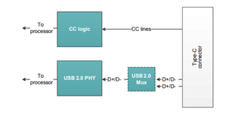
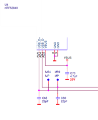
We have the nRF52840 connected to D-/D+ on a USB Type-C connector. We have a standalone IC to enable battery charging by listening at 5V on VBUS. However, when we are using USB C-USB C cables this is not working, because 5V is not supplied on the VBUS. We can solve this by adding an appropriate pullup resistor to the CC pins, but this will lead to a change in existing PCB, so I was looking at the option of using the nRF chipset to initiate the USB 2.0 PHY alternative. We are not using the USB interface today for other than charging.

Is this possible, or will this fall under the limitation of not supporting USB-IF Battery Charging spec 1.1? 

  • Hi,

    I'm not sure I understand your problem correctly. Do you mean you want the nRF5 device to supply 5V to the VBUS line? 

    Would you mind sharing a schematic that highlights the issue? 

    regards

    Jared 

  • Hi Jared

    Sorry for my bad explanation, I'll try to make it clear. We have a USB Type-C connector, but the CC pins are not in use so modern chargers are not detecting that the cable is attached to our USB port, hence not providing 5V to VBUS. As an alternative to using the CC pins, we can add support of USB 2.0 to initiate the charging.

    Below is the drawing for our connector to the left, and the connections to the nRF52840 to the right. They were on two different pages so you don't see connection between the lines, but you can see the lines called USB_DP and USB_DN is going into the nRF.

    So my question is if the nRF5 can be used to start charging using USB 2.0 standard.

  • Hi Eivind,

    Thank you for the clarification and the drawings. It made it very clear.

    USB charge is not supported by the nRF52840, It will not recognize that it's connected to a charging port and thus can not be used to start charging. 

    regards

    Jared 

  • Why have you got 22pF capacitors on the USB D+/D- data lines? These should be kept as low capacitance as possible. I think the USB 2.0 spec only allows about 10pF max for PCB, parasitics etc

    Add 5k1 resistors on both CC1 and CC2 to GND I believe. Yes, a board spin but that's the proper way so just bite the bullet. Possibly depending on the USB-C connector design you could modify existing boards as a bit of a hack to save throwing them away.

Related