This post is older than 2 years and might not be relevant anymore
More Info: Consider searching for newer posts

nRF9160 GPIO pin leakage/pull-down problem

We use our own board with both nRF52840 and nRF9160. We run into a problem trying to implement a circuit that enables the nRF9160 to reset the nRF52840. Things work fine if we disable the pinreset in nRF52840.

Background:

  • We start the nRF52840 first. It is powered with 1.8V. 
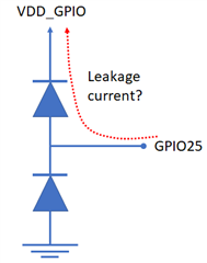
  • The nRF9160 has VDD (3.0V - 4.2V in this case) supplied. The ENABLE pin of the nRF9160 is pulled down at the start (nRF52840 enables it when needed). VDD_GPIO is not supplied when ENABLE is down.
  • The device tested uses an NRF9160-SICA-B1A sample - but it seemed that the same behaviour exists in NRF9160-SICA-B0A 

Problem: The P0.25 pin of the nRF9160 is connected to the nRESET of the nRF52840. If we enable the pinreset configuration in UICR, the internal pull-up of the nRF52840 fails to pull the pin high, the voltage raises to 0.93V - 1.05V only. It seems like the nRF9160 pulls the pin down. If the ENABLE pin of the nRF9160 is raised and VDD_GPIO supplied, the nRF9160 P0.25 goes to high-Z state and the nRF52840 pinreset pullup pulls the pin to 1.8V. It seemed that pulling ENABLE down after this leaves the reset line at 1.8V. Our system does not boot if the pinreset is enabled as the nRESET voltage is too low and the nRF52840 remains in the reset state.

I did not find this nRF9160 behavior documented anywhere. Is this the correct interpretation? Is there any difference if we switched to another pin in nRF9160? (The P0.25 has also TRACE3 function - seems unlikely but possible that it could interfere). Is there some workaround for this that would allow the nRF9160 GPIO pin to be connected to the nRESET of the nRF52840 - when nRF9160 ENABLE is kept low at boot?

Adding a pullup resistor would help to raise the voltage but it raises the current consumption way too much. 

Pertti

Parents
  • If we go through the whole setup how the MCUs are powered: the schematics part we should separate as a private ticket - would need to share and explain quite a lot of functionality.

    The connection between the P0.25 and nRESET pins has only a 100nF capacitor to the GND. (In some applications it will also have a reset button tied to this same line.) 

  • Hi Pertti,

    Response form he R&D;
    When enable is turned down, the internal power is turned off from the nRF9160 module. Because there is no operating voltage on the SoC, nRF9120, the ESD protection diodes loads the pins and therefore it only rises to diode threshold level.

    And a request for more information, It seemed that pulling ENABLE down after this leaves the reset line at 1.8V. Our system does not boot if the pinreset is enabled as the nRESET voltage is too low and the nRF52840 remains in the reset state.
    Does the level remain at 1.8V permanently or is that 1.8V just a "snapshot" of the situation?

  • Additional info:
    Leakage current on GPIO pin is like in picture below in case VDD_GPIO is at 0V (and it's impedance is low)

    Putting a series resistor between nRF9160 and nRF52840 with size >>internal pullup (=> propose >100kohm) can make nRF52 internal pullup work. But reset control from nRF91 will not work properly and there will be some leakage current flowing in the situation where nRF9160 is missing supply voltages.

    Is this sufficient information or are there more questions ?

    Regards,
    Jonathan

  • Thank you. This is in line with some more tests we did. Having such ESD diodes is what we suspected. You could consider adding this information to the documentation. We were wondering should we use ENABLE, nRESET or maybe SYSTEMOFF for what we wanted but did not find enough information for getting the first experiment right.

    We are hardly the only ones trying to use the nRF9160 for a very low-power design in this way. Seems that if we want to connect to the nRF9160 GPIO pins things that require a pull-up: to avoid leakage when ENABLE is pulled down, need to add a switch to the pin that disconnects the pin from the pull-up when ENABLE is down. 

    Now I have at hand a setup that allows easy testing of the "snapshot" question: 

    1. Our device starts with nRF9160 disabled, ENABLE low
    2. I configure the pin in the nRF52840 as an input with pull-up. The line goes to about 1V, 
    3. Turn on the nRF9160 ENABLE, the pin (P0.25) goes to high-Z state and the line goes to 1.8V with the pullup
    4. Turn off the nRF9160 ENABLE, the pin returns to about 1V, half way between the pull-up and the ESD diode "pull-down"
    5. Configure the nRF52840 pin as disconnected: power consumption reduces about 30uA
  • This at least answers the original question. 

    This additional information is interesting. The figure suggests that the leakage from P0.25 would go to the VDD_GPIO. As far as I remember in our design it should not leak to VDD_GPIO (more than what goes to about 5uF of capacitance to GND). But we will check that.

  • Pertti Kasanen said:
    We were wondering should we use ENABLE, nRESET or maybe SYSTEMOFF for what we wanted but did not find enough information for getting the first experiment right.

    We do have some improvements to do on the usability of the documentation but it is hard to get things right since there are so many different uncases and variables that will change the configuration. SYSTEMOFF is often a safe bet and will reduce consumption allot, but I don't know how often you need to be connected to LTE so there will always be a tradeoff to what is best. keeping the system on an potentially have some leakage or power down and up again and paying the cost of startup.  


    Regards,
    Jonathan

  • Just an additional comment. We had the VDD_GPIO disconnected (with a FET). 

    We made a new test for selectively connecting the VDD_GPIO to GND while ENABLE is down (and 2-3 of the nRF9160 GPIO pins are pulled-up). It increased the current consumption by about 2uA.

Reply Children
No Data
Related