This post is older than 2 years and might not be relevant anymore
More Info: Consider searching for newer posts

Triggering SAADC sampling in synchronous with GPIO HITOLOW transition.

Product: nrf52840 DK

Softdevice: 17.0.2

Hello,

I would like to start with a very humble statement that I am new to this nrf52 SoCs and would appreciate any of your help.

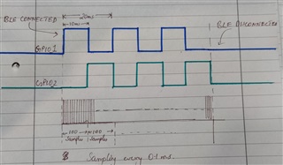
I am working on a project with a photodiode and two LEDs with different wavelengths. I would like to read the analog values from the photodiode let's say every 0.1ms. There are two gpio outputs from the nrf which toggles the LED each 10 ms. So each GPIO pins are producing 100 Hhz 50% duty cycle PWM signals but are opposite to each other. So once the LED1 is ON, LED2 is OFF and so on.

For the application, synchronization of SAADC SAMPLE START and GPIO transitions are very important. 

So I have managed to toggle both the GPIOs with 100 Hz frequency with opposite polarity with the help of a single external timer instance. Let's say NRF_DRV_TIMER_INSTANCE(1). I have used two different PPI channels to assign tasks and events. So the idea was to set the GPIO2 at a different initial state(HIGH) to obtain the result. So GPIO1 start from LOTOHIGH and GPIO2 starts from HITOLOW. Now I have assigned a different timer (NRF_DRV_TIMER_INSTANCE(2)) for the SAADC. This timer ticks at every 0.1ms to trigger the sampling. Also here I have assigned PPI channel to assign the sampling task and timer event. I am reading the value from the saadc_callback handler. 

Now I would like to know how to synchronize the operation. That is to trigger the clock or to start the sampling at the rising edge of GPIO1. 

1. How can I use the interrupt at the rising edge of the GPIO1 to trigger the SAADC sampling? This is crucial because the first 100 readings from the SAADC will be the analog value from the photosensor caused due to LED1 and the next 100 readings will be generated due to LED2.  

2. Is this approach the correct method or is there any other better method?

3. This question covers a different issue but still, I would like to ask. My application is using a BLE features to send the analog value to a central device. Values are sent to the central device inside the saadc_callback handler. If I had to start the sampling and the GPIO output state transition only after a successful connection is established with the central device, what would be the right way to program the firmware? Are there existing example codes explaining similar usage? (I believe the answer is YES. But I was not able to find any. Please help me out with this.)

Again thank you for your time and would appreciate any of your valuable suggestions. 

Karlz

Parents
  • Hi,

    1. How can I use the interrupt at the rising edge of the GPIO1 to trigger the SAADC sampling? This is crucial because the first 100 readings from the SAADC will be the analog value from the photosensor caused due to LED1 and the next 100 readings will be generated due to LED2.  

    2. Is this approach the correct method or is there any other better method?

    If GPIO1 is configured as an output in GPIOTE, you will not get any interrupt on the rising edge of this GPIO. You either need to use the event that toggles the GPIO to start the TIMER/SAADC sampling through PPI, or setup a separate GPIOTE channel as input (configured as watcher), and physically connect the output and input pins together externally.

    3. This question covers a different issue but still, I would like to ask. My application is using a BLE features to send the analog value to a central device. Values are sent to the central device inside the saadc_callback handler. If I had to start the sampling and the GPIO output state transition only after a successful connection is established with the central device, what would be the right way to program the firmware? Are there existing example codes explaining similar usage? (I believe the answer is YES. But I was not able to find any. Please help me out with this.)

    The simplest solution would be to enable the PPI channel(s) when you receive the CONNECTED event in the application, and similarly, disable the PPI channel(s) when you receive the DISCONNECTED event.

    Best regards,
    Jørgen

  • Kalrz said:
    So should I use the same timer for both SAADC and GPIOs? ( which i believe is not the solution). Or should I use a separate PPI channel to assign the two timers (timer instance 1 and 2) to each other and then use another PPI channel to assign the timer instance 2 with SAADC for triggering sample? I don't quite understand this. So can you please elaborate?

    I may have misunderstood how and when you want to sample the SAADC. Can you create a timing diagram that shows the toggling of the LEDs and when you want the SAADC sampling to happen?

    Kalrz said:
    separate GPIOTE channel as input (configured as watcher), and physically connect the output and input pins together externally.

    At the moment, I would prefer any other method without an additional external physical connection.

    If things are triggered by events over PPI, it should be possible to synchronize it with PPI forks, or multiple PPI channels, but it depends on how things are triggered, and the required timing accuracy.

Reply
  • Kalrz said:
    So should I use the same timer for both SAADC and GPIOs? ( which i believe is not the solution). Or should I use a separate PPI channel to assign the two timers (timer instance 1 and 2) to each other and then use another PPI channel to assign the timer instance 2 with SAADC for triggering sample? I don't quite understand this. So can you please elaborate?

    I may have misunderstood how and when you want to sample the SAADC. Can you create a timing diagram that shows the toggling of the LEDs and when you want the SAADC sampling to happen?

    Kalrz said:
    separate GPIOTE channel as input (configured as watcher), and physically connect the output and input pins together externally.

    At the moment, I would prefer any other method without an additional external physical connection.

    If things are triggered by events over PPI, it should be possible to synchronize it with PPI forks, or multiple PPI channels, but it depends on how things are triggered, and the required timing accuracy.

Children
  • Hai Jorgen,

    Sorry, I should have been more clear.

    Can you create a timing diagram that shows the toggling of the LEDs and when you want the SAADC sampling to happen?

    /resized-image/__size/320x240/__key/communityserver-discussions-components-files/4/7532.img.jpg 

    (Please inform me if the image is not clear enough. I am not sure about it)

    At the moment both the GPIOs are triggered via PPI using a single timer. SAADC sampling is triggered every 0.1ms using another timer through PPI. These two methods are clearly mentioned in my previous reply. Now as you can see from the timing diagram, I need my GPIO and SAADC sampling to be triggered at the CONNECTED event from the BLE application (As you suggested). How can I connect the CONNECTED event, GPIOs, and SAADC to be all triggered at the same time through PPI? Is it possible for you to provide a brief line of code just to show how it should be carried out? I am confused about where to allocate the PPI event and tasks. Is it inside the callback handler of the SAADC? 

    Thanks.

    Best regards.

  • Thanks, it is clear now.

    The CONNECTED event is a software event, so this cannot be used to trigger any tasks through PPI. You will have to trigger the tasks from software. You can also use an additional compare event to trigger the tasks through PPI very close after the event is received. If you do not require the GPIO to toggle exactly when the CONNECTED event is received, you can start the timer in software to toggle the GPIO after the first 10ms have passed.

    As far as I can see, you should be able to use the timer compare event that toggles the GPIO to trigger the START task of the timer that triggers SAADC sampling. This should trigger the first sampling 100us after the GPIO toggles. If you want to trigger a sample at the same time that the GPIO is toggled, you can also trigger the SAMPLE task from the timer event that toggles the GPIO(s). If you set a SAADC buffer size equal to the number of samples between GPIO toggling, you should be able to use the compare events from the GPIO timer to START the SAADC sampling at the regular interval that you have shown in your timing diagram.

    Kalrz said:
    I am confused about where to allocate the PPI event and tasks. Is it inside the callback handler of the SAADC?

    The address of the tasks and events are static and documented in the Registers section of each peripheral chapter in the product specifications. You should be able to configure this at any location in your code.

Related