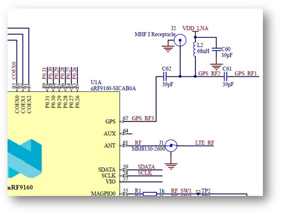
This post is older than 2 years and might not be relevant anymore
More Info: Consider searching for newer posts

Nrf9160 GPS long time to fix with healthy RF electronics

Helo Nordic support team,
I am supporting a client that has designed a product using the NRF9160 with GPS. The product has a small patch antenna mounted on the pcb board, a saw filter and a LNA upstream the GPS port of the NRF9160.

The product has been tested extensively in the open and they experience long time to fix - in some cases 10 to 15 minutes from cold start (and some time no fix at all). It was suspected that the antenna gain and match could explain long fix time due to lov SNR for the received GPS signal. The antenna match was investigated using a network analyser and found to be around -10dB RL for the GPS band.

We have compared the product respons with a Thingy:91 using a larger patch antenna with integrated LNA. This gave similar results with long time to fix (not tested as thorough as the product).

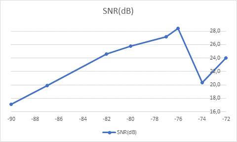
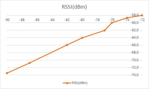
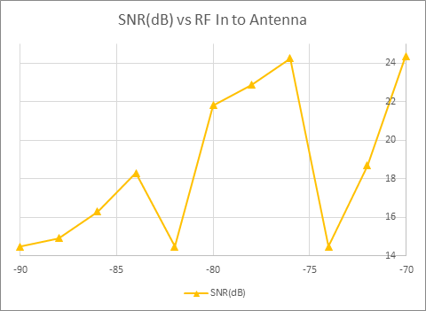
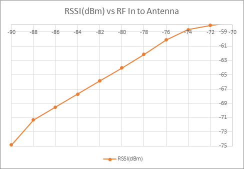
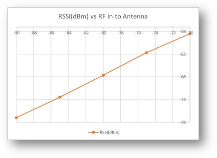
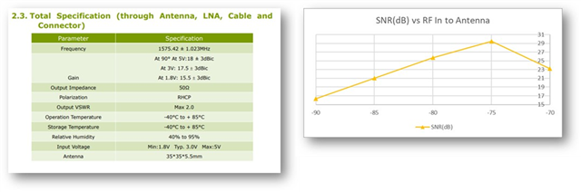
Next test was done in a lab version of an anechoic chamber called GTEM cell. It is not a perfect environment for antenna performance tests but gives a good indication on performance. Using this GTEM device with a signal source we were able to apply a -90dbm CW signal to the product (now running only with test software and battery power). The test software logged the SNR and RSSI using the AT AT%XRFTEST=2,1,-90 at command and after the test we extracted the data from the product to a log file using a J-link SEGGER with RTT Viewer. We did a similar test with the Thingy:91 with the external antenna and got similar results.

Our preliminary conclusion is that the product (and the Thingy:91) has good RF performance (around 14dB gain including LNA, SAW and antenna gain).

I tend to conclude that the long time to fix can be explained by software. 

There are no other use of the radio between GPS read, the LTE is not used.

Can the Nordic team comment on why do we experience long time to fix from cold condition even with apparently healthy RF electronics ?
Thanks,
Regards
Bjørn
Parents
  • We have made some additional tests using both the Thingy:91 with external antenna and the product we have designed based on your NRF9160.


    The Thingy has been tested using an external antenna. The Coax connector for external antenna has no longer an internal switch so we selected to remove the dc block capacitance downstream of the connector towards the internal GPS antenna. This to try to keep the 50ohm transmission line from the NRF to the external antenna. The external antenna has a LNA and the test software is configured to switch this power on (confirmed by measuring that the bias voltage is present on the external coax line).


    We have three configurations (four if you add the GPS cold start hit the pedal drive test .. : )  ). The first test was done putting the Thingy:91 w/ext ant. on the roof of my car. The car was parked at Sunland in Drammen with no cars nearby and farily open space around the site. The second test was run at the exact same spot but now with the product as the GPS receiver. The third test was done on the dashboard for both the Thingy and the product. The last test was executed by giving Thingy (and also the product) a cold start and then immidiatly driving away in order to test or get a reference measurement for a moving receiver.  


    I still have a few more tests to run before I will share the results. I will upload these test when Ithe extended test has concluded.


    In addition to these tests I have added a more dedicated test on SNR and RSSI. I put the receiver into a suitable GTEM cell and configured the lab. Signal source to give -90dBm field power at the antenna of the test device. The GTEM is EM sealed and very little exernal radiowaves can kreep into the test chamber. Could you please evaluate the data in this log file and comment on the RSSI and SNR?


    All data in the attached log files have been extracted using the JLINK and the JLinkRTTViewer.exe from Segger.


    There are two files attached:

    • gps_driver_share.zip : Code for test in the field
    • gps_rf_test_share.zip : Code to test the gps in the RF chamber
    • Chamber_test_Product_boresight_90dbm_vertical.log : log file from chamber test

     These datafiles have been modified to remove client source code.

    gps_driver_share.zip

    gps_rf_test_share.zip

    # SEGGER J-Link RTT Viewer V6.88a Terminal Log File
    # Compiled: 15:12:58 on Nov 18 2020
    # Logging started @ 14 Feb 2021 13:37:26
    00> *** Booting Zephyr OS build v2.4.0-ncs1-24-gdac3d0802faa  ***
    00> 
    00> AT response: %XRFTEST: 289,-19411
    00> 
    00> AT response: %XRFTEST: 286,-19391
    00> 
    00> AT response: %XRFTEST: 284,-19411
    00> 
    00> AT response: %XRFTEST: 283,-19391
    00> 
    00> AT response: %XRFTEST: 285,-19411
    00> 
    00> AT response: %XRFTEST: 284,-19411
    00> 
    00> AT response: %XRFTEST: 288,-19411
    00> 
    00> AT response: %XRFTEST: 287,-19411
    00> 
    00> AT response: %XRFTEST: 286,-19411
    00> 
    00> AT response: %XRFTEST: 288,-19411
    00> 
    00> AT response: %XRFTEST: 284,-19391
    00> 
    00> AT response: %XRFTEST: 288,-19391
    00> 
    00> AT response: %XRFTEST: 287,-19411
    00> 
    00> AT response: %XRFTEST: 285,-19371
    00> 
    00> AT response: %XRFTEST: 289,-19391
    00> 
    00> AT response: %XRFTEST: 289,-19371
    00> 
    00> AT response: %XRFTEST: 284,-19411
    00> 
    00> AT response: %XRFTEST: 285,-19411
    00> 
    00> AT response: %XRFTEST: 286,-19371
    00> 
    00> AT response: %XRFTEST: 286,-19391
    00> 
    00> AT response: %XRFTEST: 285,-19411
    00> 
    00> AT response: %XRFTEST: 291,-19391
    00> 
    00> AT response: %XRFTEST: 292,-19411
    00> 
    00> AT response: %XRFTEST: 287,-19391
    00> 
    00> AT response: %XRFTEST: 289,-19371
    00> 
    00> AT response: %XRFTEST: 288,-19391
    00> 
    00> AT response: %XR1
    00> 
    00> 1
    00> 
    00> Measurement: 0, snr: 289, antenna_power: -19411
    00> 
    00> Measurement: 1, snr: 286, antenna_power: -19391
    00> 
    00> Measurement: 2, snr: 284, antenna_power: -19411
    00> 
    00> Measurement: 3, snr: 283, antenna_power: -19391
    00> 
    00> Measurement: 4, snr: 285, antenna_power: -19411
    00> 
    00> Measurement: 5, snr: 284, antenna_power: -19411
    00> 
    00> Measurement: 6, snr: 288, antenna_power: -19411
    00> 
    00> Measurement: 7, snr: 287, antenna_power: -19411
    00> 
    00> Measurement: 8, snr: 286, antenna_power: -19411
    00> 
    00> Measurement: 9, snr: 288, antenna_power: -19411
    00> 
    00> Measurement: 10, snr: 284, antenna_power: -19391
    00> 
    00> Measurement: 11, snr: 288, antenna_power: -19391
    00> 
    00> Measurement: 12, snr: 287, antenna_power: -19411
    00> 
    00> Measurement: 13, snr: 285, antenna_power: -19371
    00> 
    00> Measurement: 14, snr: 289, antenna_power: -19391
    00> 
    00> Measurement: 15, snr: 289, antenna_power: -19371
    00> 
    00> Measurement: 16, snr: 284, antenna_power: -19411
    00> 
    00> Measurement: 17, snr: 285, antenna_power: -19411
    00> 
    00> Measurement: 18, snr: 286, antenna_power: -19371
    00> 
    00> Measurement: 19, snr: 286, antenna_power: -19391
    00> 
    00> Measurement: 20, snr: 285, antenna_power: -19411
    00> 
    00> Measurement: 21, snr: 291, antenna_power: -19391
    00> 
    00> Measurement: 22, snr: 292, antenna_power: -19411
    00> 
    00> Measurement: 23, snr: 287, antenna_power: -19391
    00> 
    00> Measurement: 24, snr: 289, antenna_power: -19371
    00> 
    00> Measurement: 25, snr: 288, antenna_power: -19391
    00> 
    00> Measurement: 26, snr: 286, antenna_power: -19411
    00> 
    00> Measurement: 27, snr: 292, antenna_power: -19391
    00> 
    00> Measurement: 28, snr: 284, antenna_power: -19371
    00> 
    00> Measurement: 29, snr: 285, antenna_power: -19371
    00> 
    00> Measurement: 30, snr: 284, antenna_power: -19391
    00> 
    00> Measurement: 31, snr: 289, antenna_power: -19411
    00> 
    00> Measurement: 32, snr: 288, antenna_power: -19371
    00> 
    00> Measurement: 33, snr: 286, antenna_power: -19411
    00> 
    00> Measurement: 34, snr: 290, antenna_power: -19391
    00> 
    00> Measurement: 35, snr: 289, antenna_power: -19391
    00> 
    00> Measurement: 36, snr: 286, antenna_power: -19411
    00> 
    00> Measurement: 37, snr: 286, antenna_power: -19391
    00> 
    00> Measurement: 38, snr: 288, antenna_power: -19371
    00> 
    00> Measurement: 39, snr: 286, antenna_power: -19371
    00> 
    00> Measurement: 40, snr: 290, antenna_power: -19411
    00> 
    00> Measurement: 41, snr: 293, antenna_power: -19411
    00> 
    00> Measurement: 42, snr: 287, antenna_power: -19351
    00> 
    00> Measurement: 43, snr: 289, antenna_power: -19391
    00> 
    00> Measurement: 44, snr: 291, antenna_power: -19391
    00> 
    00> Measurement: 45, snr: 283, antenna_power: -19411
    00> 
    00> Measurement: 46, snr: 287, antenna_power: -19391
    00> 
    00> Measurement: 47, snr: 286, antenna_power: -19411
    00> 
    00> Measurement: 48, snr: 290, antenna_power: -19411
    00> 
    00> Measurement: 49, snr: 289, antenna_power: -19391
    00> 
    00> Measurement: 50, snr: 291, antenna_power: -19441
    00> 
    00> Measurement: 51, snr: 290, antenna_power: -19391
    00> 
    00> Measurement: 52, snr: 288, antenna_power: -19391
    00> 
    00> Measurement: 53, snr: 289, antenna_power: -19391
    00> 
    00> Measurement: 54, snr: 291, antenna_power: -19411
    00> 
    00> Measurement: 55, snr: 292, antenna_power: -19391
    00> 
    00> Measurement: 56, snr: 290, antenna_power: -19391
    00> 
    00> Measurement: 57, snr: 290, antenna_power: -19391
    00> 
    00> Measurement: 58, snr: 292, antenna_power: -19411
    00> 
    00> Measurement: 59, snr: 293, antenna_power: -19391
    00> 
    00> Measurement: 60, snr: 286, antenna_power: -19441
    00> 
    00> Measurement: 61, snr: 289, antenna_power: -19391
    00> 
    00> Measurement: 62, snr: 290, antenna_power: -19371
    00> 
    00> Measurement: 63, snr: 289, antenna_power: -19371
    00> 
    00> Measurement: 64, snr: 286, antenna_power: -19391
    00> 
    00> Measurement: 65, snr: 290, antenna_power: -19411
    00> 
    00> Measurement: 66, snr: 286, antenna_power: -19411
    00> 
    00> Measurement: 67, snr: 290, antenna_power: -19411
    00> 
    00> Measurement: 68, snr: 295, antenna_power: -19391
    00> 
    00> Measurement: 69, snr: 297, antenna_power: -19411
    00> 
    00> Measurement: 70, snr: 290, antenna_power: -19391
    00> 
    00> Measurement: 71, snr: 288, antenna_power: -19371
    00> 
    00> Measurement: 72, snr: 292, antenna_power: -19411
    00> 
    00> Measurement: 73, snr: 288, antenna_power: -19411
    00> 
    00> Measurement: 74, snr: 291, antenna_power: -19391
    00> 
    00> Measurement: 75, snr: 287, antenna_power: -19411
    00> 
    00> Measurement: 76, snr: 290, antenna_power: -19411
    00> 
    00> Measurement: 77, snr: 293, antenna_power: -19371
    00> 
    00> Measurement: 78, snr: 290, antenna_power: -19391
    00> 
    00> Measurement: 79, snr: 292, antenna_power: -19391
    00> 
    00> Measurement: 80, snr: 294, antenna_power: -19371
    00> 
    00> Measurement: 81, snr: 290, antenna_power: -19411
    00> 
    00> Measurement: 82, snr: 289, antenna_power: -19391
    00> 
    00> Measurement: 83, snr: 291, antenna_power: -19411
    00> 
    00> Measurement: 84, snr: 290, antenna_power: -19391
    00> 
    00> Measurement: 85, snr: 295, antenna_power: -19411
    00> 
    00> Measurement: 86, snr: 294, antenna_power: -19411
    00> 
    00> Measurement: 87, snr: 290, antenna_power: -19411
    00> 
    00> Measurement: 88, snr: 295, antenna_power: -19391
    00> 
    00> Measurement: 89, snr: 293, antenna_power: -19371
    00> 
    00> Measurement: 90, snr: 294, antenna_power: -19391
    00> 
    00> Measurement: 91, snr: 291, antenna_power: -19411
    00> 
    00> Measurement: 92, snr: 292, antenna_power: -19411
    00> 
    00> Measurement: 93, snr: 294, antenna_power: -19391
    00> 
    00> Measurement: 94, snr: 286, antenna_power: -19411
    00> 
    00> Measurement: 95, snr: 293, antenna_power: -19411
    00> 
    00> Measurement: 96, snr: 285, antenna_power: -19391
    00> 
    00> Measurement: 97, snr: 287, antenna_power: -19391
    00> 
    00> Measurement: 98, snr: 293, antenna_power: -19391
    00> 
    00> Measurement: 99, snr: 290, antenna_power: -19391
    00> 
    
    # Logging stopped @ 14 Feb 2021 13:40:42
    

  • Hi,

    We also added some tests from a location in Drammen.

    The test is on a Thingy:91 with external antenna and LNA. The Thingy is placed on the rooftop of the car and 15 cold start measurements were recorded (a cold start is a power on cycle when the unit is completely disconnected from any power supplies).

    The next test is with the Thingly located on the dashboard of the car. This time we only took 5 measurements all from a cold start.

    The last test was with the product located on the dashboard. 15 tests were recorded.

      thingy (roof) :  Product (dashboard)
    1    33        52
    2    37        46
    3    21        32
    4    21        52
    5    33        43
    6    37        41
    7    38        44
    8    39        48
    9    37        42
    10  36        42
    11  29        48
    12  43        46
    13  38        52
    14  36        42
    15  38        35

          thingy (dashboard)
    1    33
    2    37
    3    30
    4    31
    5    36

    The log files from these measurement where created by connecting the JLink to the Thingy/Product. No USB ocnnection was used.

    Thanks,

    Regards

    Bjørn

    Thingy_27_2_Sundland.zip

  • Hi Jonathan,

    Thank you for your answer.

    Could you comment the data fro the GTEM cell and comment on the SNR and RSSI ?

    Thanks,

    Regards

    Bjørn 

  • So the results indicate\shows that the better the CN0 value the quicker TTFF(Time to firt fix).Better antenna leads to better CN0 values witch leads to better TTFF. 

    Device 2 seems to be much better, both in terms of TTFFs and CN0s. Is there a difference in the two devices ?

    The values you got for the thingy is as good as it gets and everything that is in the 40s range is very good. 

    Regards,
    Jonathan

  • Hi Jonathan,

    Did you get a chance to comment on tha data logger file:

    • Chamber_test_Product_boresight_90dbm_vertical.log : log file from chamber test

    thanks,

    Regards Bjørn

  • Hi Bjørn, 

    Sorry for the slow reply, but what is the gain of the LNA used? 

    The camber test summarized:
    And the values range (100 runs): 
    Antenna power:-19411 to -19371 so that would be -75.8dBm to -75.6dBm
    SNR: range from 283 to 297, that would be 17.6dB to 18.5dB


    Some feedback on the chamber test. 

    Our preliminary conclusion is that the product (and the Thingy:91) has good RF performance (around 14dB gain including LNA, SAW and antenna gain).

    So you have to account for the gain when doing the test.


    If you give -90 dBm power level in the command, have -90 dBm signal generator, and get -75dBm back as response to the AT command, it means that there is 15dB of gain between the signal generator and the nRF9160. The difference of 15dB in command's power and response indicates that the receiver is possibly saturated and the SNR result is possibly not accurate.

    Thus, in order to take the LNA gain into account they should use command

         AT%XRFTEST=2,1,-75,0 

    (set <param1> = 0) 

    Regarding the signal level setting there is also a note in the AT Guide:

    Note: It is recommended to set the signal level defined in the GPS SNR ON parameters to the
    expected signal level at the GPS antenna port of the nRF9160 SiP.

    Then the SNR should also get higher. Expected level is closer to 30dB than 20dB. The RSSI in response should be close to the value given in input.


    Regards,
    Jonathan

  • Hi Jonathan,

    Thanks for your answer.

    I am not quite sure I understand the explanation on saturated LNA. We do have a LNA, SAW filter and an antenna upstream the gps port of the nrf9160. If we apply -90dBm to the antenna port (using the TEM wave produced by the GTEM cell) and the xRFTEST gives RSSI of -76dBm. then the gain is 14dB and roughly as expected.

    My understanding of the AT%XRFTEST=2,1,-75,0 is that it should give 0dB gain? 

    Could you explain?

    Thanks,

    Regards

    Bjørn

Reply
  • Hi Jonathan,

    Thanks for your answer.

    I am not quite sure I understand the explanation on saturated LNA. We do have a LNA, SAW filter and an antenna upstream the gps port of the nrf9160. If we apply -90dBm to the antenna port (using the TEM wave produced by the GTEM cell) and the xRFTEST gives RSSI of -76dBm. then the gain is 14dB and roughly as expected.

    My understanding of the AT%XRFTEST=2,1,-75,0 is that it should give 0dB gain? 

    Could you explain?

    Thanks,

    Regards

    Bjørn

Children
  • Using this config :  AT%XRFTEST=2,1,-75,0
    the result should be close to 75dBm for the antenna power.


    since you had a offset the SNR values you got from the measurement from the chamber test there is likely a offset in the SNR value not giving the true result due to the ~15dB offset from not accounting for the LNA.

    If that maks sense ?

    Regards,
    Jonathan

  • Hi Jonathan,

    I made a few other measurements and the primary objective was to investigate if the receiver goes into saturation.

    I used AT commands through the JLINK interface to communicate with the product. The prodcut was positioned inside my GTEM cell. The signal source could be ste to have different levels of RF power.

    Test one: Using RF power levet at the GPS antenna port of -90dBm and command "at at%xrftest=2,1,-75". This gave the result 271,-18825 (SNR=17dB and RSSI=-73.5dBm).

    Then the RF signal power was increased from -90dBm up to -72dBm (using command "at at%xrftest=2,1,-75"):


                                  Antennapower(dBm)      SNR       RSSI       SNR(dB)        RSSI(dBm)

    1) RF Power = -90dBm   -90                        274        -18805      17,1             -73,5

    2) RF Power = -87dBm   -87                        318        -18104     19,9              -70,7

    3) RF Power = -82dBm   -82                        393        -16873      24,6             -65,9

    4) RF Power = -80dBm   -80                        412        -16392      25,8             -64,0

    5) RF Power = -78dBm   -78(edit from -7    434        -15881       27,1             -62,0

    6) RF Power = -76dBm   -76                        455        -15351      28,4             -60,0

    7) RF Power = -74dBm   -74                        325        -15020      20,3             -58,7

    8) RF Power = -72dBm   -72                        384        -14850      24,0             -58,0

    (Table 1)

    I also tested with "at at%xrftest=2,1,-57" with antenna power of -72dBm followed by "at at%xrftest=2,1,-53" with antenna power of -67dBm. This gave SNR 495(31dB)/RSSI -14352(-56dBm) and SNR 538(34dB)/RSSI -13093(-51dBm).

    I have added two graphs from "table 1" above.

    It appears that SNR goes into saturation but only at significant higher power than -90dBm. I cannot see evidence that the Product LNA goes into saturation at -90dBm to the antenna (in the GTEM cell).

    (Edit 18.3.2021: The LNA in these tests have been upgraded and has 3dB more gain. )

    Thanks,

    Regards

    Bjørn

  • Hi, (18.3.2021)

    We added some more test, this time of the original GSP product with standard LNA (3dB lower compared to the previous test).

    The product is located in the GTEM test chamber and with RF power to the antenna from -90dBm and increased to -70dBm. The purpose is to check if the LNA or NRF9160 hits saturation at a certain RF input power level.

    These tests where run with AT command «at at%xrftest=2,1,-75». Some tests where repeated with the highest input power and with «at at%xrftest=2,1,-55».

    Pin (dBm)

    SNR

    RSSI

    SNR(dB)

    RSSI(dBm)

    -90

    232

    -19155

    15

    -75

    -88

    239

    -18254

    15

    -71

    -86

    261

    -17804

    16

    -70

    -84

    293

    -17333

    18

    -68

    -82

    232

    -16863

    15

    -66

    -80

    349

    -16392

    22

    -64

    -78

    366

    -15911

    23

    -62

    -76

    388

    -15391

    24

    -60

    -74

    232

    -15020

    15

    -59

    -72

    299

    -14870

    19

    -58

    -70

    390

    -14760

    24

    -58

    Testet with XRFTEST=2,1,-75


    SNR at the highest input power gave some strange data. Hence the test was repeated with the highest input power levels but with XRFTEST=2,1,-55.

    Pin (dBm)

    SNR

    RSSI

    SNR(dB)

    RSSI(dBm)

    -74

    401

    -14877

    25

    -58

    -72

    400

    -14376

    25

    -56

    -70

    418

    -13875

    26

    -54


    THINGY TESTS:

    The last test I did was on the Thingy with external antenna, , SAW and LNA. Antenna type Taoglas 574R. The J2 is connected to the extern

    Pin (dBm)

    SNR

    RSSI

    SNR(dB)

    RSSI(dBm)

    -90

    261

    -19706

    16

    -77

    -85

    337

    -18555

    21

    -72

    -80

    412

    -17313

    26

    -68

    -75

    472

    -16041

    30

    -63

    -70

    371

    -14970

    23

    -58

    It has been demonstrated in earlier posts that the Thingy GPS has somewhat better GPS performance. But from these test it is not super clear why. We have seen that the external antenna used on the Thingy has better Xpol performance compared to the Product. A good Xpol antenna will give 3dB for free compared to a linear receiver antenna.

    Thank you for your support on this case Jonathan.

    Regards

    Bjorn 

  • Hi Bjørn,


    One thing that sticks out is the dips/drops that you experience. R&D replicated a the test and could not reproduce the results.

    The result is perfectly aligned with thingy results –  the SNR gets better as the signal level increases.

    There is 15.5dB headroom in the Gain control design, so it is expected that SNR starts to get worse after -60 (if -75 is used in AT command and SIP input sees -75 dBm too), but all the way from -75 to -60 it seems to get linearly better if tested like this with cable (which seems to have about 1.5 dB loss).  Since I don't have LNA on board the signal generator has 15 dB power more than the customer.
     

    Signal Gen dBm AT cmd SNR RSSI
    -77 -75 409 -20037
    -76 -75 425 -19796
    -75 -75 439 -19546
    -74 -75 453 -19286
    -73 -75 463 -19055
    -72 -75 481 -18775
    -71 -75 486 -18535
    -70 -75 505 -18284
    -69 -75 515 -18004
    -68 -75 534 -17764
    -67 -75 539 -17513
    -65 -75 561 -17013
    -63 -75 571 -16512
    -61 -75 579 -16001
    -59 -75 593 -15471
    -58 -75 583 -15230


    So other then the dips the results you have is not bad, so on thing that might be a cause of this difference is the tuning of the antenna. Have you tested, tuned and matched the antenna with propper RF equipment ?

    Regards,
    Jonathan

  • Will add a comment;

    After more internal testing from our engineers the results seems to point out hat you might ave a sub-optimal antenna design.

    • Customer's Ext-LNA + Antenna seem to give about 15...17dB gain (is it expected result with given antenna gain+ LNA gain?), which is close internal HW Ext-LNA (SKY65943-11) gain derived from RSSI rise w/ and w/o Ext LNA
    • From conducted results SNR 22.5dB at -90dBm compared to customer's radiated data SNR ~15dB at -90dBm ant power: Customer DUT's SNR missing several dB's, which could be explained by noise coupling to GPS antenna or antenna gain (again antenna gain/efficiency and LNA gain would be good to know)
    • Test with internal HW show that Ant pwr level vs SNR with and without external LNA behave as expected i.e. no SNR dips with external LNA and total RX SNR is maintained nevertheless SIP's NF rise due to AGC steps (that is important if very high gain Ext-LNA is placed in GPS frontend)
    • These CW tests are just to check RX path validity and check possible unwanted noise, true GPS signal at DUT antenna lies well below thermal noise <-113dBm/1.023MHz which is amplified by ext-LNA before RFIC

    So our recommended prosess for designed new HW is as follows.

    1) Conducted RF performance verification in lab: verify HW path from antenna feed to nRF9160 SIP GPS input is performing as expected in terms of ext-LNA control, in/out matchings and impedance control of routing. 

    2) Passive GPS antenna measurements: measure antenna radiation pattern and efficiency (=aka passive antenna measurements) to understand a bit how the device might perform. Do we have e.g. these results available?

    3) Combined performance: to verify conducted and antenna solution performance adds-up as expected when combined. Here e.g. EMI from other parts of HW design (LEDs, other active ICs,..) may cause new issues not detected in 1) nor 2). (in proper anechoic chamber = consistent/known environment)

    Input for such testing is given in https://infocenter.nordicsemi.com/topic/struct_nrf91/struct/nrf91_guidelines.html?cp=2_0_7 
      => https://infocenter.nordicsemi.com/topic/nwp_034/WP/nwp_034/nwp_034_rf_perf_test.html 
      => https://infocenter.nordicsemi.com/topic/nwp_033/WP/nwp_033/nwp_033_intro.html 


    Regards,
    Jonathan

Related