This post is older than 2 years and might not be relevant anymore
More Info: Consider searching for newer posts

Debugging SAADC with variable voltage input

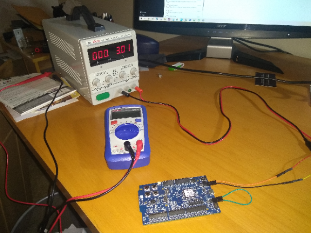
I am finding that the voltage measurement is about .52 volts off when measuring Vdd   I have set up a power supply and connected it to external power.  My saadc is set up with 14 bit resolution, a gain of 4, an internal reference (.6v).  I set oversample to try to improve results, as well.  With the usb connected, the saadc is reporting about 2.74 volts and my understanding is the usb is regulated to 3.3 volts.  To get the voltage I am dividing the EasyDMA result by 4551.1  (1/6 / .6) * 2^14

My solution is to subtract .52v off the measured voltage.  I was trying to get better insight into what is going on by adjusting my power supply and seeing what the reported voltage is.  Unfortunately, the USB cable power source conflicts with the external power supply so I cannot use external power to vary the voltage.  Attempting to rectify that, I removed the 5V supply from the USB cable but it appears the JLink connection requires the 5V source and JLink failed. 

I am looking for help on how to debug the adc and saadc and get around the supply source problem.

I realize that subtracting .52v is not a good way to solve this problem as something fundamental must be wrong.  Here is the saadc code and the routine to test the voltage:

static void saadc_init(void){

// Configure SAADC singled-ended channel, Internal reference (0.6V), and 1/6 gain.
NRF_SAADC->CH[0].CONFIG = (SAADC_CH_CONFIG_GAIN_Gain1_6 << SAADC_CH_CONFIG_GAIN_Pos) |
(SAADC_CH_CONFIG_MODE_SE << SAADC_CH_CONFIG_MODE_Pos) |
(SAADC_CH_CONFIG_REFSEL_Internal << SAADC_CH_CONFIG_REFSEL_Pos) |
(SAADC_CH_CONFIG_RESN_Bypass << SAADC_CH_CONFIG_RESN_Pos) |
(SAADC_CH_CONFIG_RESP_Bypass << SAADC_CH_CONFIG_RESP_Pos) |
(SAADC_CH_CONFIG_TACQ_5us << SAADC_CH_CONFIG_TACQ_Pos);
(SAADC_CH_CONFIG_BURST_Enabled << SAADC_CH_CONFIG_BURST_Pos);

// Configure the SAADC channel with VDD as positive input, no negative input(single ended).
NRF_SAADC->CH[0].PSELP = SAADC_CH_PSELP_PSELP_VDD << SAADC_CH_PSELP_PSELP_Pos;
NRF_SAADC->CH[0].PSELN = SAADC_CH_PSELN_PSELN_NC << SAADC_CH_PSELN_PSELN_Pos;

// Configure the SAADC resolution.
NRF_SAADC->RESOLUTION = SAADC_RESOLUTION_VAL_14bit << SAADC_RESOLUTION_VAL_Pos;

// Configure result to be put in RAM at the location of "result" variable.
NRF_SAADC->RESULT.MAXCNT = 1;
NRF_SAADC->RESULT.PTR = (uint32_t)&result;

// No automatic sampling, will trigger with TASKS_SAMPLE.
NRF_SAADC->SAMPLERATE = SAADC_SAMPLERATE_MODE_Task << SAADC_SAMPLERATE_MODE_Pos;
NRF_SAADC->OVERSAMPLE = SAADC_OVERSAMPLE_OVERSAMPLE_Over8x << SAADC_OVERSAMPLE_OVERSAMPLE_Pos;

// Enable SAADC (would capture analog pins if they were used in CH[0].PSELP)
NRF_SAADC->ENABLE = SAADC_ENABLE_ENABLE_Enabled << SAADC_ENABLE_ENABLE_Pos;

// Calibrate the SAADC
NRF_SAADC->TASKS_CALIBRATEOFFSET = 1;
while (NRF_SAADC->EVENTS_CALIBRATEDONE == 0);
NRF_SAADC->EVENTS_CALIBRATEDONE = 0;
while (NRF_SAADC->STATUS == (SAADC_STATUS_STATUS_Busy <<SAADC_STATUS_STATUS_Pos));
}

static void low_battery_test(){

// Start the SAADC and wait for the started event.
NRF_SAADC->TASKS_START = 1;
while (NRF_SAADC->EVENTS_STARTED == 0);
NRF_SAADC->EVENTS_STARTED = 0;

// Do a SAADC sample, will put the result in the configured RAM buffer.
NRF_SAADC->TASKS_SAMPLE = 1;
while (NRF_SAADC->EVENTS_END == 0);
NRF_SAADC->EVENTS_END = 0;

// Convert the result to voltage
// Result = [V(p) - V(n)] * GAIN/REFERENCE * 2^(RESOLUTION)
// Result = (VDD - 0) * ((1/6) / 0.6) * 2^14
// VDD = Result / 4551.1
precise_result = (float)result / 4551.1f;

//trip low battery if voltage is less than 2.5 volts
if(precise_result < BATTERY_LOW-.52){

//update the transmit packet content
batt_low = true;

}

int main(void){

  saadc_init();

  low_battery_test();

}

Parents
  • Hi,

    I am having some problems making sense of the situation. You write that measurements are about 0,52 V off. That is far too much though, and as you are using the internal reference the measurement results should be independent of the supply voltage. This leads me to an important question. How do you know that measurements are off? Have you measured on the VDD with an oscilloscope while the SAADC operation takes place and verified it? Without knowing more about your HW I can only speculate, but it could be that some external circuitry, potentially win combination with a high current, makes the VDD voltage lower than you think. So I believe the first think to do is to verify that your target value is correct.

  • I am driving Vdd with an external calibrated power supply (Dr Meter 305DM).  Supply is stable.

    I have tried a number of configurations to test this.

    Test A) If I connect the USB cable and drive power off of it, the reported voltage is about 2.7 to 2.8 volts.  Since this is a regulated input it should be reporting 3.3 volts unless the current draw is too high as you mentioned.

    Test B) USB connected as in A and 3.5 volt stable power supply added to External input.  Reported voltage is the same as in A. 

    Test C) USB disconnected and stable power supply connected.  My application changes signal transmitted via bluetooth when reported voltage at Vdd is 2.5 volts.  I adjust the power supply voltage until I get the signal to flip.  The signal flip occurs between 3.12 and 3.15 volts as measured at the power supply.

    I hope this explains the situation.

Reply
  • I am driving Vdd with an external calibrated power supply (Dr Meter 305DM).  Supply is stable.

    I have tried a number of configurations to test this.

    Test A) If I connect the USB cable and drive power off of it, the reported voltage is about 2.7 to 2.8 volts.  Since this is a regulated input it should be reporting 3.3 volts unless the current draw is too high as you mentioned.

    Test B) USB connected as in A and 3.5 volt stable power supply added to External input.  Reported voltage is the same as in A. 

    Test C) USB disconnected and stable power supply connected.  My application changes signal transmitted via bluetooth when reported voltage at Vdd is 2.5 volts.  I adjust the power supply voltage until I get the signal to flip.  The signal flip occurs between 3.12 and 3.15 volts as measured at the power supply.

    I hope this explains the situation.

Children
  • Hi,

    mark waldin said:
    I am driving Vdd with an external calibrated power supply (Dr Meter 305DM).  Supply is stable.

    Can you confirm that it is actually Vdd you drive directly, and not some other point on your board, so that there are some other components between where you supply the board and the VDD pins on the IC? Have you measured on the VDD pin itself?

    This still does not make sense to me so I would like to ask a bit more:

    • Can you share schematics and layout of your board?
    • Can you share a drawing and photo of your measurement setup?
    • Have you tested other boards in case there is a issue with the specific board you are testing?
  • I am testing using the NRF 52DK.  Power supply is connected to the External Power pins on the board.  No other items involved in the set up.  I have tested another board with similar results.

    As you asked I measured Vdd directly and I do see a voltage of 3.3 when the power supply is set at 3.5 and a voltage of 2.8 with the power supply set at 3.0 volts.  I double checked the power supply voltage.  I understood the external power supply pins to be directly connected to Vdd so I do not understand the .2 volt drop.  Just to be certain I checked the read out of the power supply and it is accurate.  

    I am using the embedded JLink on the board and it does not function without USB cable power supplied which is why I ran test C above.

  • Hi,

    I do not see where you measure the current, but I see it is not on the nRF current measurement port. That is where you need to measure the current in order to not get contributions from other parts of the PCB, including the onboard debugger (which will consume some current even if it is not fully operating on external supply. See Power supply and Measuring current in the DK documentation for details.

Related