
Hi!
We are trying to maximize the battery life of our product and have come across this white paper: High pulse drain impact on CR2032 coin cell battery capacity which suggest flattening the peak current draws should help.
To that end, we measured an nRF52833 current draw in 3 use cases:
1. No capacitors added to board.
2. a 47uF capacitor added in parallel to the battery.
3. 2x 47uF capacitors added in parallel to the battery.
here are the results, in graphs obtained from the PPK:
No capacitors added:
In system off- ~1uA average with ~12uA peaks.
While transmitting (There is some overhead of current because of a peripheral but its current draw is more or less constant, so it can be ignored):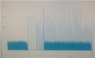
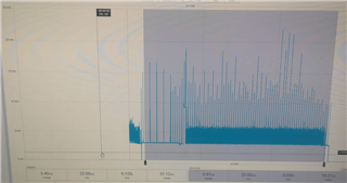
47uF capacitor added:
In system off- ~1uA average with ~4uA peaks.
While transmitting (There is some overhead of current because of a peripheral but its current draw is more or less constant, so it can be ignored):
2x47uF capacitor added:
In system off- ~1uA average with ~3.1uA peaks.
While transmitting (There is some overhead of current because of a peripheral but its current draw is more or less constant, so it can be ignored):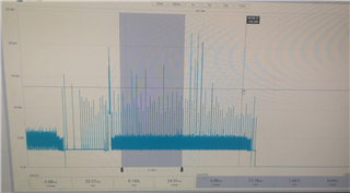
Conclusion:
Adding capacitors in parallel definitely reduces the current peaks in system off mode, and it looks like it also helps reduce the current peaks while transmitting.
Questions:
1. Is there a 'recommended' capacitor value to add in parallel to the battery which anyone has tested? If not, is there a way to calculate the capacitance needed for a given Tx, load size etc?
2. Is there a more 'accurate' way to measure the impact a capacitor has on current peaks than to roughly average the result given out by the PPK?
3. When selecting a capacitor, what are the values we must pay close attention to? We've selected for a low ESR and calculated the current draw an advertising event will require, and tried matching the capacitance after DC-bias to match the required charge.
Any insight will be helpful.
Thanks!
