The device we are using is nRF51822. It uses a bootloader from the Nordic SDK 11.0.0
The boot-loader we are using for the nRF51822 has several blocks of code in the SystemInit() function that are related to Product Anomaly Notificatiions:
- PAN 26 "System: Manual setup is required to enable the use of peripherals"
- PAN 59 "MPU: Reset value of DISABLEINDEBUG register is incorrect"
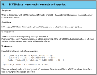
- PAN 76 "System: Excessive current in sleep mode with retention"
This code in SystemInit() has functions that are reading values from the following locations::
- 0xF0000FE0
- 0xF0000FE4
- 0xF0000FE8
- 0xF0000FEC
For example:
if ((((*(uint32_t *)0xF0000FE0) & 0x000000FF) == 0x1)
These addresses are in the reserved area of the memory map. I cannot find any registers in the nRF51 Reference Manual corresponding to these addresses.
The relevant file is: system_nrf51.c. The contents of this file are attached below.
It appears that this code if trying to determine the type of chip or chip variant and initialize some peripheral registers. However, even the peripheral register addresses don't all make sense.
I cannot find any Product Anomaly Notifications on the Nordic website.
We are concerned that our code is trying to access invalid memory locations.
Can you explain what is going on here?
/* Copyright (c) 2015, Nordic Semiconductor ASA
 * All rights reserved.
 *
 * Redistribution and use in source and binary forms, with or without
 * modification, are permitted provided that the following conditions are met:
 *
 *   * Redistributions of source code must retain the above copyright notice, this
 *     list of conditions and the following disclaimer.
 *
 *   * Redistributions in binary form must reproduce the above copyright notice,
 *     this list of conditions and the following disclaimer in the documentation
 *     and/or other materials provided with the distribution.
 *
 *   * Neither the name of Nordic Semiconductor ASA nor the names of its
 *     contributors may be used to endorse or promote products derived from
 *     this software without specific prior written permission.
 *
 * THIS SOFTWARE IS PROVIDED BY THE COPYRIGHT HOLDERS AND CONTRIBUTORS "AS IS"
 * AND ANY EXPRESS OR IMPLIED WARRANTIES, INCLUDING, BUT NOT LIMITED TO, THE
 * IMPLIED WARRANTIES OF MERCHANTABILITY AND FITNESS FOR A PARTICULAR PURPOSE ARE
 * DISCLAIMED. IN NO EVENT SHALL THE COPYRIGHT HOLDER OR CONTRIBUTORS BE LIABLE
 * FOR ANY DIRECT, INDIRECT, INCIDENTAL, SPECIAL, EXEMPLARY, OR CONSEQUENTIAL
 * DAMAGES (INCLUDING, BUT NOT LIMITED TO, PROCUREMENT OF SUBSTITUTE GOODS OR
 * SERVICES; LOSS OF USE, DATA, OR PROFITS; OR BUSINESS INTERRUPTION) HOWEVER
 * CAUSED AND ON ANY THEORY OF LIABILITY, WHETHER IN CONTRACT, STRICT LIABILITY,
 * OR TORT (INCLUDING NEGLIGENCE OR OTHERWISE) ARISING IN ANY WAY OUT OF THE USE
 * OF THIS SOFTWARE, EVEN IF ADVISED OF THE POSSIBILITY OF SUCH DAMAGE.
 *
 */

/* NOTE: Template files (including this one) are application specific and therefore expected to
   be copied into the application project folder prior to its use! */

#include <stdint.h>
#include <stdbool.h>
#include "nrf.h"
#include "system_nrf51.h"
#include "nrf_gpio.h"


/*lint ++flb "Enter library region" */


#define __SYSTEM_CLOCK      (32000000UL)     	/* nRF51822 devices in Taiyo Yuden BLE module use System Clock Frequency 32MHz */
//#define __SYSTEM_CLOCK      (16000000UL)     /*!< nRF51 devices use a fixed System Clock Frequency of 16MHz */


static bool is_manual_peripheral_setup_needed(void);
static bool is_disabled_in_debug_needed(void);
static bool is_peripheral_domain_setup_needed(void);
void SetResetXtalFreq_32MHz(void);
void test_pin_output(void);


#if defined ( __CC_ARM )
    uint32_t SystemCoreClock __attribute__((used)) = __SYSTEM_CLOCK;
#elif defined ( __ICCARM__ )
    __root uint32_t SystemCoreClock = __SYSTEM_CLOCK;
#elif defined   ( __GNUC__ )
    uint32_t SystemCoreClock __attribute__((used)) = __SYSTEM_CLOCK;
#endif

void SystemCoreClockUpdate(void)
{
    SystemCoreClock = __SYSTEM_CLOCK;
}

void SystemInit(void)
{
	/* Configure reset XTAL frequency*/
	SetResetXtalFreq_32MHz();


    /* If desired, switch off the unused RAM to lower consumption by the use of RAMON register.
       It can also be done in the application main() function. */

    /* Prepare the peripherals for use as indicated by the PAN 26 "System: Manual setup is required
       to enable the use of peripherals" found at Product Anomaly document for your device found at
       https://www.nordicsemi.com/. The side effect of executing these instructions in the devices
       that do not need it is that the new peripherals in the second generation devices (LPCOMP for
       example) will not be available. */
    if (is_manual_peripheral_setup_needed())
    {
        *(uint32_t volatile *)0x40000504 = 0xC007FFDF;
        *(uint32_t volatile *)0x40006C18 = 0x00008000;
    }

    /* Disable PROTENSET registers under debug, as indicated by PAN 59 "MPU: Reset value of DISABLEINDEBUG
       register is incorrect" found at Product Anomaly document for your device found at
       https://www.nordicsemi.com/. There is no side effect of using these instruction if not needed. */
    if (is_disabled_in_debug_needed())
    {
        NRF_MPU->DISABLEINDEBUG = MPU_DISABLEINDEBUG_DISABLEINDEBUG_Disabled << MPU_DISABLEINDEBUG_DISABLEINDEBUG_Pos;
    }

    /* Execute the following code to eliminate excessive current in sleep mode with RAM retention in nRF51802 devices,
       as indicated by PAN 76 "System: Excessive current in sleep mode with retention" found at Product Anomaly document
       for your device found at https://www.nordicsemi.com/. */
    if (is_peripheral_domain_setup_needed()){
        if (*(uint32_t volatile *)0x4006EC00 != 1){
            *(uint32_t volatile *)0x4006EC00 = 0x9375;
            while (*(uint32_t volatile *)0x4006EC00 != 1){
            }
        }
        *(uint32_t volatile *)0x4006EC14 = 0xC0;
    }

	test_pin_output();						// DEBUG   Just toggle a pin


}


static bool is_manual_peripheral_setup_needed(void)
{
    if ((((*(uint32_t *)0xF0000FE0) & 0x000000FF) == 0x1) && (((*(uint32_t *)0xF0000FE4) & 0x0000000F) == 0x0))
    {
        if ((((*(uint32_t *)0xF0000FE8) & 0x000000F0) == 0x00) && (((*(uint32_t *)0xF0000FEC) & 0x000000F0) == 0x0))
        {
            return true;
        }
        if ((((*(uint32_t *)0xF0000FE8) & 0x000000F0) == 0x10) && (((*(uint32_t *)0xF0000FEC) & 0x000000F0) == 0x0))
        {
            return true;
        }
        if ((((*(uint32_t *)0xF0000FE8) & 0x000000F0) == 0x30) && (((*(uint32_t *)0xF0000FEC) & 0x000000F0) == 0x0))
        {
            return true;
        }
    }

    return false;
}

static bool is_disabled_in_debug_needed(void)
{
    if ((((*(uint32_t *)0xF0000FE0) & 0x000000FF) == 0x1) && (((*(uint32_t *)0xF0000FE4) & 0x0000000F) == 0x0))
    {
        if ((((*(uint32_t *)0xF0000FE8) & 0x000000F0) == 0x40) && (((*(uint32_t *)0xF0000FEC) & 0x000000F0) == 0x0))
        {
            return true;
        }
    }

    return false;
}

static bool is_peripheral_domain_setup_needed(void)
{
    if ((((*(uint32_t *)0xF0000FE0) & 0x000000FF) == 0x1) && (((*(uint32_t *)0xF0000FE4) & 0x0000000F) == 0x0))
    {
        if ((((*(uint32_t *)0xF0000FE8) & 0x000000F0) == 0xA0) && (((*(uint32_t *)0xF0000FEC) & 0x000000F0) == 0x0))
        {
            return true;
        }
        if ((((*(uint32_t *)0xF0000FE8) & 0x000000F0) == 0xD0) && (((*(uint32_t *)0xF0000FEC) & 0x000000F0) == 0x0))
        {
            return true;
        }
    }

    return false;
}


/* Set reset XTAL frequency to 32MHz
 *
 * The body of this function will only run once.
 * The first time the boot-loader runs, after the flash memory has been erased
 * and programmed, the UICR registers are blank unless they have been written during
 * flash programming.  This function will program the XTALFREQ register the first time
 * the boot-loader runs if it doesn't have the correct value.  After that the XTALFREQ
 * register will have the correct value and the initial "if" statement will always be false.
 *
 * A reset is required after writing to the XTALFREQ register.  UICR registers are read on
 * reset and changes to these registers have no effect until the next reset.
 *
 * Alternatively can write to UICR XTALFREQ register during flash programming:
 *	nrfjprog --memwr 0x10001008 --val 0xFFFFFF00
 *
 */
void SetResetXtalFreq_32MHz(void)
{

	if (NRF_UICR->XTALFREQ == 0xFFFFFFFF)
	{
		// Enable NVM write access
		NRF_NVMC->CONFIG = NVMC_CONFIG_WEN_Wen << NVMC_CONFIG_WEN_Pos;
		while (NRF_NVMC->READY == NVMC_READY_READY_Busy)
		{ }

		NRF_UICR->XTALFREQ = 0xFFFFFF00;			// 32MHz

		// Set NVM access to read-only
		NRF_NVMC->CONFIG = NVMC_CONFIG_WEN_Ren << NVMC_CONFIG_WEN_Pos;
		while (NRF_NVMC->READY == NVMC_READY_READY_Busy)
		{ }

		NVIC_SystemReset();					// Changes take effect after reset
	}
}


/*lint --flb "Leave library region" */