This post is older than 2 years and might not be relevant anymore
More Info: Consider searching for newer posts

Low power PWM vs. app_pwm vs. hardware pwm driver?

SDK 14.2, NRF52840, S140

Hi,

Thank you so much in advance for answering my very long question. I am a little confused by the low power pwm example and app_PWM documentation and have some questions:

1) The pwm handler is called very frequently  -- is it called on each app timer tick? Is that 32768 times per second? Why is the timer configured as a single_shot, if the timeout needs to be called so repetitively?

 err_code = app_timer_create(p_pwm_instance->p_timer_id, APP_TIMER_MODE_SINGLE_SHOT, pwm_timeout_handler); // from low_power_pwm.c line 177

2) The pwm handler, however, seems to only be responsible for changing the duty cycle of the pin (I am pwm-ing an LED). Does this mean that if I don't want to change the duty cycle of the LED (that is, if I want to keep the same duty cycle always), does this mean I don't need the pwm handler? Or I still need it, but it can be an empty function? 

3) If I understand properly, the bitmask is supposed to be (1 << PIN_NUMBER)? So if I want to PWM GPIO P0.15, then I have to set bitmask = (1 << 15)? 
What if I wanted to PWM a pin in P1? 

4) It seems like the higher the duty cycle, the dimmer the LED gets. Is that right? This seems backwards. What units are the period and duty cycle in, and how is duty cycle defined relative to period? Is {period = 100, duty cycle = 50} functionally the same as {period = 200, duty cycle = 100}? How do these numbers relate to the timer -- are they ticks? 

5) The LED doesn't seem to be at a very constant brightness level while it is being PWM'd; every so often, I will get a brighter flash, which is a problem because it makes the light distractingly uneven. This is especially evident when the LED is relatively dim. The bright pulses are kind of like this: ______-_______---______---______. Why does this happen?

6) If I am turning on and off different LEDs, and I don't want them to be on all at the same time, before, I would call nrf_gpio_pin_set(LED1); nrf_gpio_pin_clear(LED2); 
Now, do I have to change these to low_power_pwm_start(LED1); low_power_pwm_stop(LED2); ? Would that result in the same behavior -- e.g, LED1 turning on while LED2 turns off, and when each is on, it is PWM'd to the correct respective level (as set by low_power_pwm_init and duty_set)? 

----

Here are my questions about the app_pwm, so I can make a more informed decision about which to choose. 

7) I notice that I need TIMER0 and TIMER1 to both be enabled, even if I am PWM-ing only one LED. I copied the code from the SDK PWM example, which uses TIMER1 for both LEDs. What is TIMER0 for then? If I want to PWM 3 LEDs with 3 different duty cycles, and have them be on and off at different times, it seems like I need a separate timer for each one (3 timers). And if I wanted them to all have the same duty cycle always, the only way to group them up is to use a 2 channel PWM and a separate 1 channel PWM (2 timers). Is this right?

8)  Is the equivalent of nrf_gpio_pin_set(LED1); nrf_gpio_pin_clear(LED2); using the app_pwm to do this: 

while (app_pwm_channel_duty_set(&PWM1, 0, 100) == NRF_ERROR_BUSY);

while (app_pwm_channel_duty_set(&PWM2, 0, 0) == NRF_ERROR_BUSY);

// where both are set to APP_PWM_POLARITY_ACTIVE_HIGH

The behavior I am experiencing is: 

  • if I have only LED1 set to be PWM'd, calling  nrf_gpio_pin_set(LED2); nrf_gpio_pin_clear(LED1); and also nrf_gpio_pin_set(LED1); nrf_gpio_pin_clear(LED2); seems to work, in that LED2 is turned on to full brightness while LED1 is turned off, and then LED2 is turned off while LED1 is turned on to the PWM brightness. 
  • If I have both LED1 and LED2 set to be PWM'd, nrf_gpio_pin_set/clear() don't work anymore. Calls to _set() and _clear() don't do anything. For example, in the following code, where PWM1 is config'd for LED1, and PWM2 is config'd for LED2, both LED1 and LED2 stay on indefinitely:
    while (app_pwm_channel_duty_set(&PWM1, 0, 100) == NRF_ERROR_BUSY);	// start off at 100% duty cycle
    while (app_pwm_channel_duty_set(&PWM2, 0, 50) == NRF_ERROR_BUSY);
    nrf_gpio_pin_clear(LED2);

9) I am confused that there are 4 different compare channels specified here (PWM Module documentation, p. 263). But each PWM instance can only have 2 channels, based on the code. EDIT: It looks like the hardware PWM HAL module is something completely different. Is there an example for how to use it? What are the benefits/drawbacks for each of the 3 PWM options (lpp, app_pwm, hardware pwm)? 

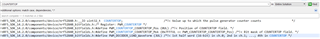
I notice the app PWM library lets you specify period in us, and also duty cycle out of 100%. Does this mean there are possibly rounding errors (even if they are small) when specifying a period that doesn't correspond with a frequency that is an even divisor of the clock frequency? I also assume that the duty cycle gets translated to a compare value, and that this may result in some rounding as well -- is this the case? I am wondering if it is possible to utilize the full dynamic range of the PWM hardware feature, which seems like it has 15-bit resolution. is it possible to specify COUNTERTOP and the COMPARE register values directly? 

I searched but didn't see that COUNTERTOP was even referenced in the app_pwm library, so maybe I am misunderstanding how this works:

10) Related to #9, I thought duty cycle is a number out of 100, but I see that app_pwm_duty_t is a uint16_t. But if I set duty cycle = 5000, somehow app_pwm_channel_duty_get(...) shows that the 5000 got turned into 84. how did this happen, and why is app_pwm_duty_t a uint16? 

Thanks!

  • Hi,

    Sorry for the late reply but I've been out of office lately.

    nordev said:

    By default, when I embed it in my own code, it looks like 0 = brightest & COUNTERTOP = off. 

    In the HAL example, it was the opposite (0 = off, 0x8000 = brightest). But I cannot tell how this was set. I thought it was via the below code: 

    but adding NRF_DRV_PWM_PIN_INVERTED to the pins in my code seem to have no effect at all. For example, setting channel 0 of .output pin to 17 or 17 | NRF_DRV_PWM_PIN_INVERTED both result in 0 = brightest and 32767 = off. I am using a custom board with a separate RGB LED & nrf52840, sdk 14.2. Do you know how I can change it so that 0 is off? 

     Would you mind sharing your code so I could see how you implemented this?

    regards

    Jared 

  • Here is code:

    static nrf_drv_pwm_t m_pwm0 = NRF_DRV_PWM_INSTANCE(0);	 // #PWM_HAL
    static nrf_pwm_values_individual_t m_demo1_seq_values;	 // #PWM_HAL
    static nrf_pwm_sequence_t const    m_demo1_seq =		 // #PWM_HAL
    {
        .values.p_individual = &m_demo1_seq_values,
        .length              = NRF_PWM_VALUES_LENGTH(m_demo1_seq_values),
        .repeats             = 0,
        .end_delay           = 0
    };
    
    static void pwm_demo(void)	 // #PWM_HAL
    {
        NRF_LOG_INFO("PWM (hardware) Demo");
    
        nrf_drv_pwm_config_t const config0 =
        {
            .output_pins =
            {
    			LED_RED,
    			LED_GREEN,
    			LED_BLUE,
    			NRF_PWM_PIN_NOT_CONNECTED
            },
            .irq_priority = APP_IRQ_PRIORITY_LOWEST,
            .base_clock   = NRF_PWM_CLK_2MHz,
            .count_mode   = NRF_PWM_MODE_UP,
            .top_value    = 32767,
            .load_mode    = NRF_PWM_LOAD_INDIVIDUAL,
            .step_mode    = NRF_PWM_STEP_AUTO
        };
        APP_ERROR_CHECK(nrf_drv_pwm_init(&m_pwm0, &config0, NULL));
    
        m_demo1_seq_values.channel_0 = 32767;	// R
        m_demo1_seq_values.channel_1 = 1000;	// G
        m_demo1_seq_values.channel_2 = 32767;	// B
    
        (void)nrf_drv_pwm_simple_playback(&m_pwm0, &m_demo1_seq, 1,
                                          NRF_DRV_PWM_FLAG_LOOP);
    }

    The result is that R & B are off, and G is on pretty bright, but not max bright. Note, this is on a custom PCB. NRF52840, SDK 14.2

    I have a null handler because I don't need to make adjustments after a sequence is done, the sequence is just setting the duty cycle to one constant level. 

  • Hi,

    nordev said:

    Also, I saw the example code use 0x8000 (demo 2, seq 1), but I thought the highest that should be possible is 0x7FFF (32767) because only 15 bits are available to set the brightness. How come 0x8000 is valid / possible?

    The 16 bits seq value consists of two parts, the polarity and the duty cycle. The 15th bit is the polarity, while the last 15 bits (14th-0th) is the duty cycle. 0x8000 is 0b1000000000000000 in binary. Which means that the first edge within the PWM period is falling, because the 15th bit is 1. The 15 bits(14th-0th) that decides the duty cycle is effectively 0, which means that the PWM will be using 0 duty cycle, effectively not toggling during the whole period. 

    Regarding your code, try switching the 15th bit and see if the polarity changes In your project. In addition, I would like to recommend that you instead of using LEDs connect a Logical analyzer. The logical analyzer would make it much easier to see changes in both polarity and duty cycle.

    Have a good weekend.

    Jared 

  • Hi Jared,

    Thanks for the reply. I see what you're saying and understand in theory, but it doesn't seem to square with the pwm driver example. Based on what you say, 0 should be first edge rising + 0 duty cycle, which should be fully on (which is what I am experiencing). But in the example, 0 is off and 0x8000 is on -- it is backwards from what you said.

    Here is an excerpt from demo2 in the example:

    I think this is the case because the example inverts the pins: 

    But when I copy this in my own code, nothing changes, as I mentioned above:

    NRF_DRV_PWM_PIN_INVERTED to the pins in my code seem to have no effect at all. For example, setting channel 0 of .output pin to 17 or 17 | NRF_DRV_PWM_PIN_INVERTED both result in 0 = brightest and 32767 = off

    I have also used a logic analyzer, and it verifies the effects I notice with my naked eye. The duty cycle is correct, it is just backwards from the way I hoped to specify it. 

  • I also ran into another issue with this:

    I am trying to have different kinds of LED blinks to indicate errors. Most of the time, the LED will be "constant" red, blue, or green (not blinking, but may be PWM'd to some duty cycle. I switch between the R, G, B by calling set_led_pwm() as defined below, and this works fine.

    However, it does NOT work well when I try to switch to BLINKING_BLUE. I use a different PWM instance. 

    I have two probelms:

    1) Every time I start the blinking sequence, which is almost exactly a copy of demo3 inside the pwm_driver example, the code stops with <error> app: ERROR 8 [NRF_ERROR_INVALID_STATE] on this line:
    APP_ERROR_CHECK(nrf_drv_pwm_init(&m_pwm1, &config, NULL)); 

    Usually, after hitting this point, the LED eventually starts blinking though. How do I find the cause of the invalid state and fix it? Is it a problem that I don't have a "sequence done" callback? 

    2) If I have, say, BLUE_BLINKING on and then I try and turn BLUE_ON (constant blue), I get a weird result where they kind of add to each other -- there is a base level of blue on, and then it "blinks" brighter blue every fraction of a second, instead of being either solid blue (BLUE_ON) or blinking on and off (BLUE_BLINKING). Basically, both sequences seem to run at the same time. How do I turn a looping sequence off, if I don't know exactly how many times I want it to repeat? Each of the LED sequences should be triggered by an event, and when a new sequence starts, any other sequence should turn off.

    #define PWM_ENABLED 1
    #define PWM0_ENABLED 1
    #define PWM1_ENABLED 1
    
    static nrf_drv_pwm_t m_pwm0 = NRF_DRV_PWM_INSTANCE(0);	// #PWM_HAL
    static nrf_drv_pwm_t m_pwm1 = NRF_DRV_PWM_INSTANCE(1);	// #PWM_HAL
    
    const uint16_t red_max = 0x0;
    const uint16_t green_max = 0x6700;
    const uint16_t blue_max = 0x5200;
    const uint16_t off = 0x8000;
    
    static void blink_blue()
    {
    	nrf_drv_pwm_config_t const config =
        {
            .output_pins =
            {
                LED_BLUE,							// channel 0
                NRF_DRV_PWM_PIN_NOT_USED,           // channel 1
                NRF_DRV_PWM_PIN_NOT_USED,           // channel 2
                NRF_DRV_PWM_PIN_NOT_USED,           // channel 3
            },
            .irq_priority = APP_IRQ_PRIORITY_LOWEST,
            .base_clock   = NRF_PWM_CLK_125kHz,
            .count_mode   = NRF_PWM_MODE_UP,
            .top_value    = 0x7FFF,
            .load_mode    = NRF_PWM_LOAD_COMMON,
            .step_mode    = NRF_PWM_STEP_AUTO
        };
        APP_ERROR_CHECK(nrf_drv_pwm_init(&m_pwm1, &config, NULL));
    
        // This array cannot be allocated on stack (hence "static") and it must
        // be in RAM (hence no "const", though its content is not changed).
        static uint16_t /*const*/ seq_values[] =
        {
    		blue_max,
            blue_max,
    		off,
            off,
        };
        nrf_pwm_sequence_t const seq =
        {
            .values.p_common = seq_values,
            .length          = NRF_PWM_VALUES_LENGTH(seq_values),
            .repeats         = 0,
            .end_delay       = 0
        };
    
        (void)nrf_drv_pwm_simple_playback(&m_pwm1, &seq, 1, NRF_DRV_PWM_FLAG_LOOP);
    }
    
    void set_led_pwm(led_pwm_evt_type_t led_evt)	 // #PWM_HAL
    {
    	switch(led_evt)	 // TODO: led_evt should be an enum
    	{
    		case(RED_ON):
    			m_pwm_seq_values.channel_0 = red_max;
    			m_pwm_seq_values.channel_1 = off;
    			m_pwm_seq_values.channel_2 = off;
    			nrf_drv_pwm_simple_playback(&m_pwm0, &m_pwm_seq, 1, NRF_DRV_PWM_FLAG_LOOP);
    			break;
    		
    		case(GREEN_ON):
    			m_pwm_seq_values.channel_0 = off;
    			m_pwm_seq_values.channel_1 = green_max;	
    			m_pwm_seq_values.channel_2 = off;
    			nrf_drv_pwm_simple_playback(&m_pwm0, &m_pwm_seq, 1, NRF_DRV_PWM_FLAG_LOOP);
    			break;
    		
    		case(BLUE_ON):
    			m_pwm_seq_values.channel_0 = off;
    			m_pwm_seq_values.channel_1 = off;
    			m_pwm_seq_values.channel_2 = blue_max;
    			nrf_drv_pwm_simple_playback(&m_pwm0, &m_pwm_seq, 1, NRF_DRV_PWM_FLAG_LOOP);
    			break;
    
    		case(BLUE_BLINKING):
    //			blink_blue();
    			break;
    
    		default: 
    			NRF_LOG_ERROR("invalid LED code, LED unchanged");
    			break;
    	}
    }

Related