This post is older than 2 years and might not be relevant anymore
More Info: Consider searching for newer posts

TWI and BLE integration test

Dear, manager.

Hi,

I am currently testing the use of TWI and BLE together.

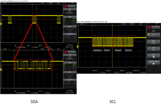
However, Data (24bit) is received and read through TWI every 4ms. BLE is only initialized, and TWI data becomes strange by simply turning on BLE, whether it is initialization or transmission.

I receive TWI 3 times each 8bit, but there seems to be no data.

Example)

Data1 Data2 Data3
56 155 135
56 116 66
56 154 128
56 155 62
56 173 131
56 120 179
56 99 95
56 201 53
0 11 98
0 11 64
0 11 41
0 11 43
0 11 158
0 11 139
0 11 81
0 11 81


How do I get the correct data?

I would appreciate your reply.

Thank you.

Regards.

Parents
  • So it works fine with no BLE?

    Have you used an analyser or scope to see what's happening on the TWI lines?

    Which pins are you using?

  • First, thank you for the answer.

    I using a P0.14 and P0.15.

    When the TWI line is checked using the scope, it is displayed fine.

    And it works fine without BLE.

    #define TWI_SCL 15
    #define TWI_SDA 14

  • thank you for reply.

    When I read TWI I use the code below.

    void twiInit()
    {
      //TWI init function
      //TWI disable
      NRF_TWI0 -> ENABLE = 0;
    
      //TWI Pin map
      NRF_TWI0 -> PSELSCL = TWI_SCL;
      NRF_TWI0 -> PSELSDA = TWI_SDA;
    
      //frequency set
      NRF_TWI0 -> FREQUENCY = 0x06680000; //400kHz
      //NRF_TWI0 -> FREQUENCY = 0x01980000; //100kHz
    
      //TWI interrupt disable
      NRF_TWI0 -> INTENCLR = 0xFFFFFFFF;
    
      //Communication enable
      NRF_TWI0 -> ENABLE = 5;
    
      //Event clear
      NRF_TWI0 -> EVENTS_RXDREADY = 0;
      NRF_TWI0 -> EVENTS_TXDSENT = 0;
    }
    
    
    void ReadData(uint8_t reg_addr)
    {
      NRF_TWI0 -> ADDRESS = TI_address;  //Slave device set address
      NRF_TWI0 -> TASKS_STARTTX = 1;  //sned start
      NRF_TWI0 -> TXD = reg_addr; //send the read register address
      while(!NRF_TWI0 -> EVENTS_TXDSENT){}  //wait ACK
      NRF_TWI0 -> EVENTS_TXDSENT = 0;   //reset event flag
    
      NRF_TWI0 -> ADDRESS = TI_address;  //Slave device set address
      NRF_TWI0 -> TASKS_STARTRX = 1; //recive start
      while(NRF_TWI0 -> EVENTS_BB == 0){}  //wait Byte Boundary
      NRF_TWI0 -> EVENTS_BB = 0;  //reset BB flag after recive
      while(NRF_TWI0 -> EVENTS_RXDREADY == 0){} //wait read
      NRF_TWI0 -> EVENTS_RXDREADY = 0; //reset RXDREADY flag
      readData1 = NRF_TWI0 -> RXD;  //bling data buffer
    
      while(NRF_TWI0 -> EVENTS_BB == 0){}  //wait Byte Boundary
      NRF_TWI0 -> EVENTS_BB = 0;  //reset BB flag after recive
      while(NRF_TWI0 -> EVENTS_RXDREADY == 0){} //wait read
      NRF_TWI0 -> EVENTS_RXDREADY = 0; //reset RXDREADY flag
      readData2 = NRF_TWI0 -> RXD;  //bling data buffer
    
      while(NRF_TWI0 -> EVENTS_BB == 0){}  //wait Byte Boundary
      NRF_TWI0 -> EVENTS_BB = 0;  //reset BB flag after recive
      NRF_TWI0 -> TASKS_STOP = 1;   //NACK recive befor recive final data
      while(NRF_TWI0 -> EVENTS_RXDREADY == 0){} //wait read
      NRF_TWI0 -> EVENTS_RXDREADY = 0; //reset RXDREADY flag
      readData3 = NRF_TWI0 -> RXD;  //bling data buffer
    }
    

    The code that receives and handles an interrupt every 4ms is as follows. (Expressed in abbreviated form.)

    Interrupt handler() //4ms event
    {
        data_EN = 1;
    }
    
    Main()
    {
        if(data_EN == 1)  //Sensor Data ready, Data read
        { 
          data_EN = 0;
          //FIFO_PHASE, Data converter------------------------
          for(int j = 0; j < 4; j++)
          {
            ReadData(0xFF);
            sign = readData1 & 0xC0;  //0b11000000
            readData1 = readData1 & 0x3F;
            if(sign == 0xC0)
            {
              SensorData[j].TestData = -((readData1 << 16) + (readData2 << 8) + readData3);
            }
            else if(sign == 0x00)
            {
              SensorData[j].TestData = (readData1 << 16) + (readData2 << 8) + readData3;
            }
            data[j] = ((double)(SensorData[j].TestData) * (double)0.0005722045898);
          }
          //---------------------------------------------------
        }
    }

    Interrupt occurs every 4ms, receives a variable from the interrupt, reads and processes TWI data.

    When BLE is initialized and advertising starts or data is sent, the TWI data becomes strange.

    And changing the advertising interval to 1 (625 us) seems to be okay. However, BLE is not available.

    And even if the advertising time is reduced, it is thought that the problem will occur again during transmission.

    And when taken with a scope, it looks like the pictures below.

    When I look at the clock graph, it seems that the data comes in correctly might.

    please help, i need you help.

    Thank you.

    Regards.

  • So your scope is an Agilent DSOX1204A:

    It can do protocol decoding!

  • Can you also output the readData1, readData2, and readData3 to terminal?

    Kenneth

  • It's listed as a table in the first question, or are you referring to something else?

  • Okey, I just saw the code you suppled were using both 'data' and 'readData', so just wanted to make sure that the values you listed were the actual twi data ('readData'), and not a calculation of twi data ('data'). 

    I think next step is really to decode those twi data on a logic analyzer. I do not see how BLE can interfere here.

    Kenneth

Reply Children
Related