
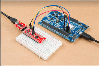
Hi,
I am trying to test the uart exemple on nrf52840 using external debugging as shown in figure but it doesn't function !!!!
are there any modifications that need to be added compared to the internal debugging mode or is it the same thing?
Hi,
I am trying to test the uart exemple on nrf52840 using external debugging as shown in figure but it doesn't function !!!!
are there any modifications that need to be added compared to the internal debugging mode or is it the same thing?


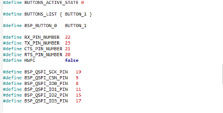
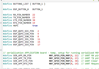 and it works in the segger terminal using RTT but the serial communication does not take place,