This post is older than 2 years and might not be relevant anymore
More Info: Consider searching for newer posts

nRF52805 pin matching

Hi

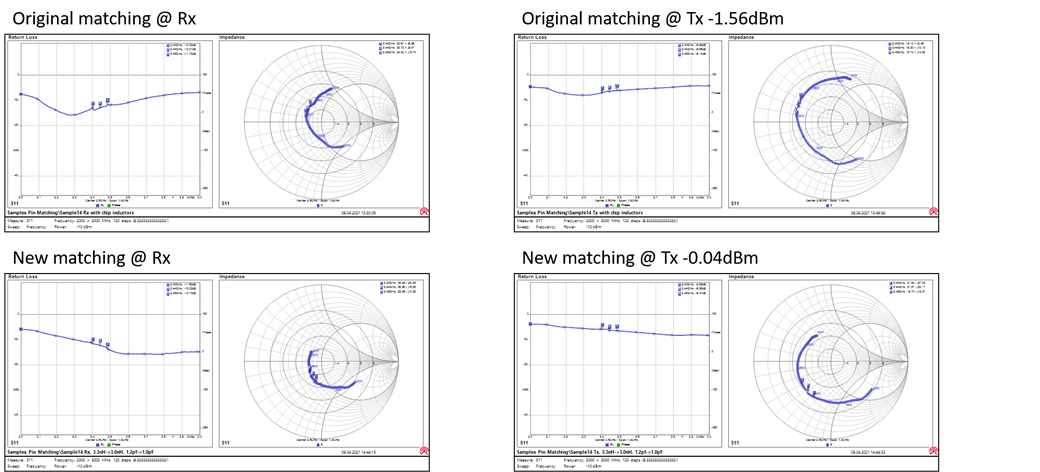
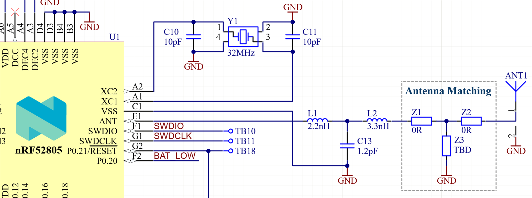
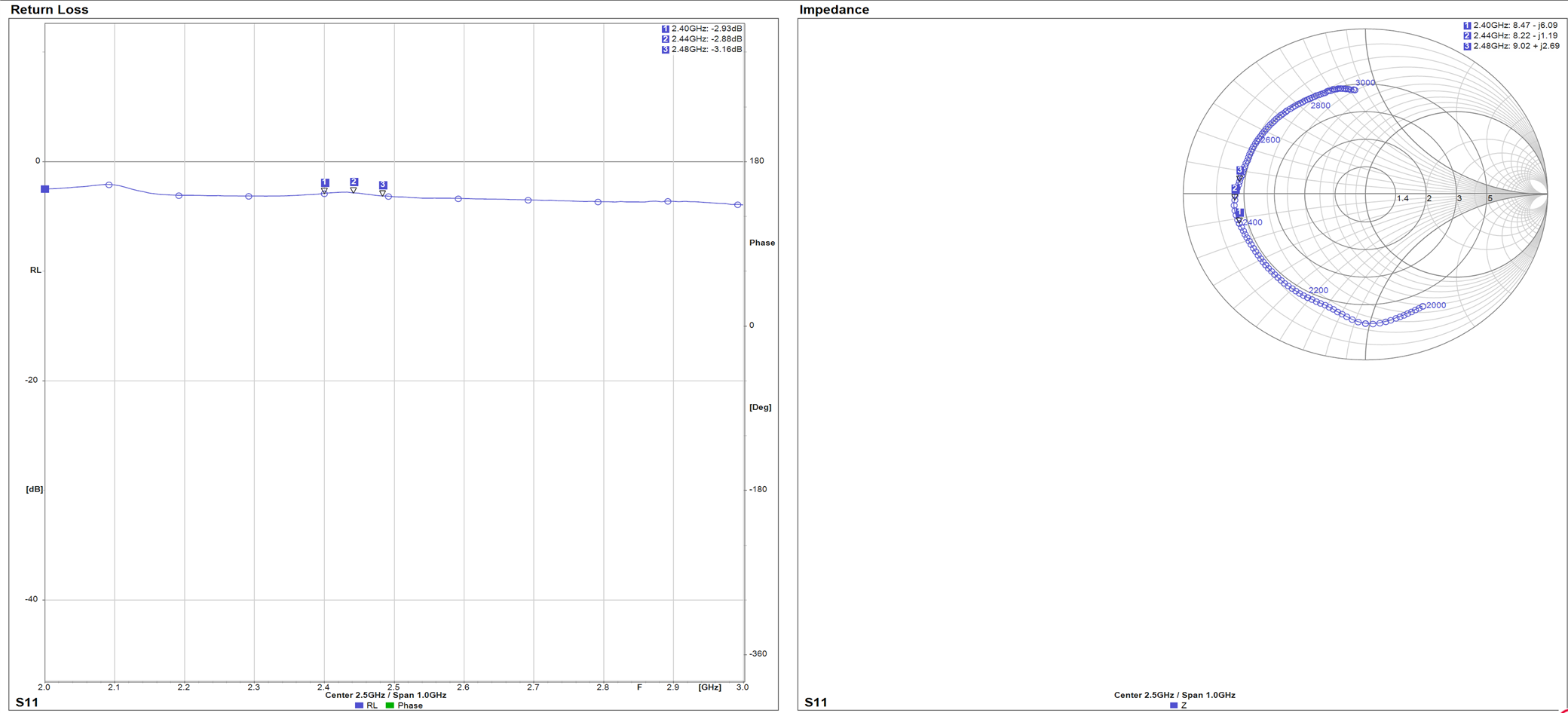
We would like to adjust the pin matching of our nRF52805 design since the measured S11 coefficients in Tx mode are not very good (well above -3dB). The values for the pin matching and harmonic filter components are selected according to the reference design, we use 0402 RF components from Murata. The output power measured after L1, L2, C13 is only -1.56dBm when the chip is set to CW mode and configured to 0dBm output power.

Question:

How do we adjust the pin matching components without changing the behaviour of the low pass filter? can you provide step-by-step instructions or tools for calculating? I think this is an important topic for other developers and projects as well.

If you need further information please let me know!

Thanks & best regards

Rashid

RF components:

Pin matchin components

Pin matching in Tx mode:

Pin matching in Tx mode

Pin matching in Rx mode:

Pin matching Rx mode

Parents
  • Hi,

    If you are measuring conducted it will probably differ from radiated testing, so it is only a somewhat accurate whey to tune.  When it comes to choosing the component values it is not that simple, it will differ from design to design and HW layout will effect the result. 

    There is a limit to of effective simulation and calculation is when it comes to the final product. We find it best and most efficient to start with the recommended values from the reference design and then we do one component at the time, increase of decrees in value, or different component type, like form a different manufacturer. Sometimes it even helps to rotate the components(inductors) 180 degrees to filter the harmonics. So we change one parameter at the time while we measure the harmonics and output power, there will (hopefully)be some combination that provides god output power and reduce the harmonics as well. 
    So we tune the radio by trail and error testing.

    feel free to ask for more if anything is unclear.

    Regards,
    Jonathan

  • Hi Jonathan
    Thanks for your reply, yes I did conducted measurements.

    I reduced L2 from 3.3nH to 3.0nH and C13 from 1.2pF to 1.0pF and the conducted power increased from -1.56dBm to -0.04dBm!! The total radiated power (TIG measured over 3 planes) increased by 1.2dB (2.402GHz), 2.6dB (2.440GHz) and 2.0dB (2.480GHz). The harmonics are well below -50dBc which is good.

    So I'm quiet happy with the result, next I will do receiver sensitivity measurements to make sure Rx mode is not negatively impacted.

    Is there anything else I must keep an eye on before going into approval ?

    One interesting fact:

    Simply looking at the S11 coefficients it doesn't seem obvious that the matching is improved at all but the power measurement clearly shows an improvement (as you said in your reply). Find the comparison of the S11 measurements below. Do you have a logical explanation for this?

    Pin matching comparison

    Best regards

    Rashid

  • Usually good TX means results in RX performance also, and radiated testing will result in differences but you should be in the right ballpark now that the conducted measurements are done. 

    I don't have a logical explanation for the graphs other then that you can see a difference but that's why we measure harmonics and power output, it is the best indicator and easier to see improvements.

    Regards,
    Jonathan

Reply Children
No Data
Related