This post is older than 2 years and might not be relevant anymore
More Info: Consider searching for newer posts

52 gpio input without pull

hi support team,

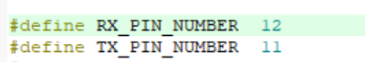
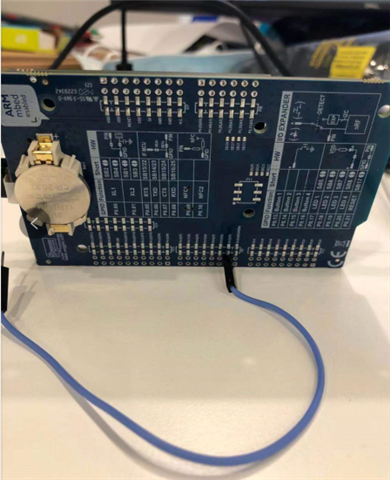
customer using 52 gpio p0.26 as input, but config it as no pull in software, strangely there is no pull up in the schematic layout, only 10 nf capacity connected between the p0.26 and ground。

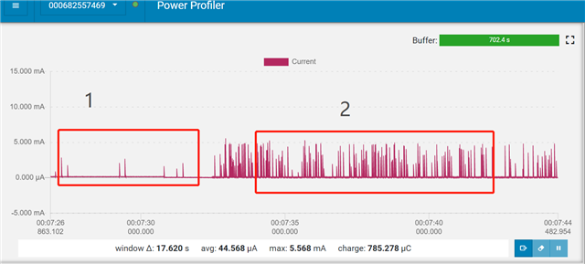
After testing, customer find out that there is a leakage current after about 50 minutes, the current varies with the time, reach at 1.5 mA.

normally i would suggest customer to config with pull-up.

but how to analyse this situation, we need to explain this to customer.

i am not going to say that the capacity is discharging, i don't understand where this comes from.

Regards,

William.

Parents
  • Hi,


    Is that pin set to a defined level by the external device that drives the P0.26 GPIO?


    Kind regards,

    Håkon

  • yes Alseth,

    there is one button that has pull up, so they use on pull in config, but customer occasionally removed it, which causes the gpiote input floating status.

    and you may still try upper code, and will find that there will be an abnormal current in idle status comparing to NRF_GPIO_PIN_PULLUP

    as i can see, GPIOTE input floating status has leakage current, until there is defined level of that pin

    Regards,

    William.

  • Hi,


    If the pin floats, the event and thus the interrupt handler gpiote_event_handler can be triggered, causing excessive current.

    Please ensure that connected inputs, especially ones that are interrupt enabled, are pulled to a defined level.


    Kind regards,

    Håkon

  • hi Alseth,

    we are on the edge of collapse, and we couldn't understand how chip process such kind of testing.

    here is my tesing with power profile in pca10040,as below.

    step1 there in no conducting wire connected to the gpiote pin p0.12,(also power consumption is wired)

    step 2,add a conducting wire to that pin. the power consumption is different.

    by the way i can see that the code is entering gpiote handler interupt.

    1. to avoid the influence of other part of board, i select pin 12 as input, as below.

    and step2 is as below, p0.12 is not connected to anything.

    and power consumption is as below.

    Thanks in advance.

    William.

  • Hi William,

    If a GPIO floats, meaning that the input is at a undefined level; it will draw more power, especially when you also route a interrupt to this signal.

    Floating input is not something that is specific to nRF devices, but all microcontrollers. It is your job as the developer to ensure that no pins float, as floating inputs will cause excessive current consumption.


    There's many forum posts on this matter, on this forum and many others out there, as well as articles and papers. Search with the keyword "floating inputs".


    Again; please ensure that your connected inputs are pulled to a defined level.

    Kind regards,

    Håkon

Reply
  • Hi William,

    If a GPIO floats, meaning that the input is at a undefined level; it will draw more power, especially when you also route a interrupt to this signal.

    Floating input is not something that is specific to nRF devices, but all microcontrollers. It is your job as the developer to ensure that no pins float, as floating inputs will cause excessive current consumption.


    There's many forum posts on this matter, on this forum and many others out there, as well as articles and papers. Search with the keyword "floating inputs".


    Again; please ensure that your connected inputs are pulled to a defined level.

    Kind regards,

    Håkon

Children
Related