This post is older than 2 years and might not be relevant anymore
More Info: Consider searching for newer posts

nrf52840's P0.21 cannot be used as libuarte's uart RX?

Hello, Nordic & all:

    I have a problem when use P0.21 as the libuarte's uart RX( base on libuarte example/sdk17.0.2) for my custom nrf52840 board, I looked up the reference of nRF52840_PS and found the follow:
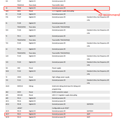
P0.08 have no recommend , P0.21 is recommended as QSPI , but my custom board don't use it as my QPSI, that means I can use it as my libuarte's uart RX, am I right?

Unfortunately, I can‘t receive anything from PC via serial port, then I change to default P0.08, It works fine.

Can you help me? what's wrong with my pin configure, or how can I make P0.21 work fine for libuarte's uart RX?

Thanks a lot! 

Parents
  • Hi, 

    I don't see any reason why P0.21 can't be used as uart RX, if you are using the nRF52840-DK then the P0.21 is by default routed to external memory IC, so you need to cut and solder some solder bridges as indicated on the back of the nRF52840-DK in that case. However, if you are using your own board, then I don't expect that is the problem. Are you able to toggle the P0.21 pin as a normal GPIO just to check it electrically?

    Kenneth

  • Hi, Kenneth:

    Thanks for your quickly reply!

    Yes, I configured P0.21 as normal output pin to set(or clear ) the electric level, It can work fine. 

  • Sorry, but it doesn't make any sense, do you have a nRF52840-DK you can use for comparison?

    Kenneth

  • Hi, Kenneth:

        I'm very sorry to reply so late because I was focus on another important thing that time;

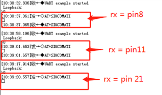
        According to your suggest, I verify this on nRF52840DK (SDK17.0.2) this via serial tool, and the result is:

    1、the default configure:TX=PIN6, RX=PIN8 , result is OK;

    2、custom configure:TX=PIN6, RX=PIN11, result is OK;

    3、custom configure:TX=PIN6, RX=PIN21, result is FAIL;

    The follow is all my changed place :

    //#define RX_PIN_NUMBER  8
    #define RX_PIN_NUMBER  21
    #define RX_PIN_NUMBER  11
    
    #define TX_PIN_NUMBER  6
    //#define TX_PIN_NUMBER  19
    #define CTS_PIN_NUMBER 7
    #define RTS_PIN_NUMBER 5
    #define HWFC           true
    
    //#define BSP_QSPI_SCK_PIN   19
    #define BSP_QSPI_CSN_PIN   17
    #define BSP_QSPI_IO0_PIN   20
    //#define BSP_QSPI_IO1_PIN   21
    #define BSP_QSPI_IO2_PIN   22
    #define BSP_QSPI_IO3_PIN   23
     

    and the test log is:

    Can you test on your environment and verify? why the pin21 can not used as the liburate RX?

    Thanks very much and look forward to your reply.

  • Hi,

    If you flip the nRF52840-DK over, you can find the P0.21 is by default connected to memory. You need to change some solder bridges as shown on the back side of the nRF52840-DK.

    Kenneth

  • Kenneth:

           Thanks for your reply,

           Yes, I understand what you mean : the nrf52840DK can not use P0.21 as uart RX unless change its hardware;

           However, I use my custom board, and It's P0.21 wasn't used for any external hardware, when I use it for libuarte, It didn't work either.

  • I am not sure what the problem is here, you would need to try and fail a bit.

    For instance finding out if it's only P0.21 that is problematic may be a good point to start. It could for instance be that the example you are using have also enabled P0.21 to be used by another peripheral, so you may need to find if there are other drivers or libraries in your project that have (by default or accident) use the same pin P0.21.

    It could also be interesting to see if P0.21 can be used as TX, this could give some indication on whether it may be something driving the pin externally that prevent it to work as intended as RX (e.g. soldering).

    You can also try to add a pull-up on the P0.21 just to see if that make a difference, since a floating P0.21 can be interpreted as framing error, making the code to assert. 

    Overall, try and fail a bit, you will eventually find out why it does not work. Maybe you have done other changes to the example project that somehow prevent the application to work as intended, so going back to the default example project as-is from the nRF5 SDK, and only change the RX pin may be something to try.

    Kenneth

Reply
  • I am not sure what the problem is here, you would need to try and fail a bit.

    For instance finding out if it's only P0.21 that is problematic may be a good point to start. It could for instance be that the example you are using have also enabled P0.21 to be used by another peripheral, so you may need to find if there are other drivers or libraries in your project that have (by default or accident) use the same pin P0.21.

    It could also be interesting to see if P0.21 can be used as TX, this could give some indication on whether it may be something driving the pin externally that prevent it to work as intended as RX (e.g. soldering).

    You can also try to add a pull-up on the P0.21 just to see if that make a difference, since a floating P0.21 can be interpreted as framing error, making the code to assert. 

    Overall, try and fail a bit, you will eventually find out why it does not work. Maybe you have done other changes to the example project that somehow prevent the application to work as intended, so going back to the default example project as-is from the nRF5 SDK, and only change the RX pin may be something to try.

    Kenneth

Children
No Data
Related