
Hi, what is the nRF52DK UART, for the nRF52832, flow control when using the ble_app_uart_pca10040_s132 example? It appears to be possible interrupt driven based on data received (UART to UART)?
As shown in this figure - assuming that level shift from 3.3v to 5v is already done but not shown for clarity.
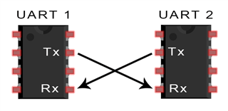
I am using the nRF52832 UART to communicate with an external Parallax RFID Read/Write RFID module UART and need to know if the nRF52832 flow control is as shown in the C code from ble_app_uart_pca10040_s132. I am assuming that CTS and RTS are not needed between the nRF52832 UART and the PIC16F723A microcontroller used on the Parallax RFID module.
/**@brief  Function for initializing the UART module.
 */
/**@snippet [UART Initialization] */
static void uart_init(void)
{
    uint32_t                     err_code;
    app_uart_comm_params_t const comm_params =
    {
        .rx_pin_no    = RX_PIN_NUMBER,
        .tx_pin_no    = TX_PIN_NUMBER,
        .rts_pin_no   = RTS_PIN_NUMBER,
        .cts_pin_no   = CTS_PIN_NUMBER,
        .flow_control = APP_UART_FLOW_CONTROL_DISABLED,
        .use_parity   = false,
In addition, from the nrf52DK User Guide: To ensure that the UART lines are not affected by the interface MCU, the solder bridges for these signals can be cut and later resoldered if needed. This might be necessary if UART without HWFC is needed while P0.05 (RTS) and P0.07 (CTS) are used for other purposes. So I assume that I should cut these to avoid any potential complications.
Thanks for any input/confirmation.
