I am initializing an SPI master to talk to ADXL362 accelerometer using NRF51-DK.
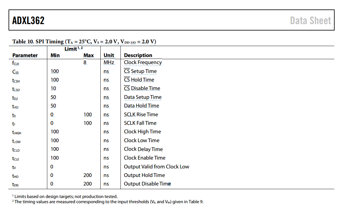
Datasheet page 19: www.analog.com/.../ADXL362.pdf
No matter what I do connected or disconnected, I always get 0xFF back. Makes no difference changing transfer speed, MSB or LSB, IRQ priority or anything. So I have some questions to clarify.
Code
void Spi_Initialize()
{
	spi_master_config_t spi_config = SPI_MASTER_INIT_DEFAULT;

#if defined(SPI_MASTER_0_ENABLE)
	spi_config.SPI_Pin_SCK = SPIM0_SCK_PIN;
	spi_config.SPI_Pin_MISO = SPIM0_MISO_PIN;
	spi_config.SPI_Pin_MOSI = SPIM0_MOSI_PIN;
	spi_config.SPI_Pin_SS = SPIM0_SS_PIN;
#elif defined(SPI_MASTER_1_ENABLE)
	spi_config.SPI_Pin_SCK = SPIM1_SCK_PIN;
	spi_config.SPI_Pin_MISO = SPIM1_MISO_PIN;
	spi_config.SPI_Pin_MOSI = SPIM1_MOSI_PIN;
	spi_config.SPI_Pin_SS = SPIM1_SS_PIN;
#endif /* SPI_MASTER_ENABLE */

	spi_config.SPI_CONFIG_ORDER = SPI_CONFIG_ORDER_LsbFirst; // :     SPI_CONFIG_ORDER_MsbFirst);
	spi_config.SPI_CONFIG_CPOL = SPI_CONFIG_CPOL_ActiveHigh;
	spi_config.SPI_CONFIG_CPHA = SPI_CONFIG_CPHA_Leading;
	spi_config.SPI_Freq = SPI_FREQUENCY_FREQUENCY_M1;
	//spi_config.SPI_PriorityIRQ = APP_IRQ_PRIORITY_HIGH;

	uint32_t result = spi_master_open(SPI_MASTER_HW, &spi_config);
	APP_ERROR_CHECK(result);

	spi_master_evt_handler_reg(SPI_MASTER_HW, spi_master_event_handler);

	Adxl362_Setup();
}
I set SPI_MASTER_0_ENABLE in the makefile and make sure it is compiled with -DSPI_MASTER_0_ENABLE . Code runs fine, and no appearent hard faults while debugging, or sending the data through bluetooth.
-
Datasheet says "The SPI timing scheme follows CPHA = CPOL = 0." spi_config.SPI_CONFIG_CPOL = SPI_CONFIG_CPOL_ActiveHigh; and spi_config.SPI_CONFIG_CPHA = SPI_CONFIG_CPHA_Leading; mean this? The actual #define values are 0, but high sounds like 1 to me? What is correct? isn't this "mode 0" ?
-
When connecting "CS" from the ADXL362 to the NRF51-DK "SEL" Pin (24), does this mean that NRF51-DK will send CS 1 and 0 before and after each command automatically? In arduino etc you need to do this manually. Or does "SEL" on the NRF51-DK have another meaning? There's like 100 different words for "chip select" it seems like :)
-
Pin 24 is also "LED 4". Does this mean that any CS output from ADXL362 will make it light up or the other way around? It is constantly lit. Should I disable this?
I am really stuck, and wonder if I have accidentally fried the ADXL362. Thanks!
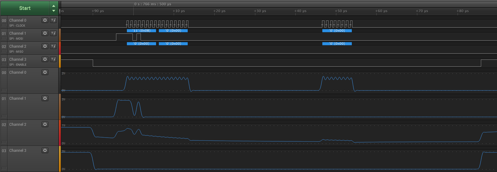
UPDATE: I got a hold of a logic analyzer. Here is my output:

What's going on here. OK, there is some noise from the clock into MISO, but it is completely dead. Shouldn't the clock be sent when getting a reply?
Success = 0 = OK.
static uint16_t Adxl362_Read(unsigned reg)
{
	uint8_t buf[4];
	uint16_t rxcnt;

	buf[0] = ADXL34X_CMD_READ;
	buf[1] = reg;

	if (reg & REG_2B) {
		rxcnt = 2;
	}
	else {
		rxcnt = 1;
		buf[3] = 0;
	}

	uint32_t status = spi_master_send_recv(SPI_MASTER_HW, &buf[0], 2, &buf[2], rxcnt);

	APP_ERROR_CHECK(status);


	return (uint16_t)buf[2];
}
My current settings aside from pins are:
spi_config.SPI_CONFIG_ORDER = SPI_CONFIG_ORDER_LsbFirst;
spi_config.SPI_CONFIG_CPOL = SPI_CONFIG_CPOL_ActiveHigh;
spi_config.SPI_CONFIG_CPHA = SPI_CONFIG_CPHA_Leading;
spi_config.SPI_Freq = SPI_FREQUENCY_FREQUENCY_M1;
Any ideas?
Update 2:
Here's a screenshot of sending 3 bytes where the 3rd now is 0xFF. Which seems delayed a lot. I read that the SPI buffer is only 2 bytes, but is 30 µs too much of a separation? Also it seems to be dead with both LSB first and MSB first even when sending the dummy 1 byte.
I am using a ble uart sample with advertising etc with one ADC on another pin, can the IRQs and timers interfere with the SPI?
Here are the timings. Does NRF adhere to these timings?