We just received a PPK2 and have used it in several configurations to test a custom nrf52832 board that runs on a 3v lithium coin cell.
When connected in the following manner, the device measures values in amp meter mode that are similar to our averaging multimeter:
Device + ============ [ PPK2 VOUT | PPK2 VIN ] =========== ( Battery + | Battery - ) ============= Device -
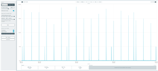
And we are getting the curves that seem to match what we expect our device to be doing at the times during which they appear. There is no common ground connection between the PPK2 and the DUT.
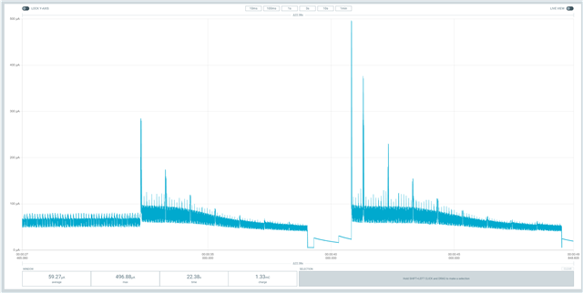
This was fine, but then we we tried to remove the battery and power the DUT with the PPK2 as a source, with the DUT Vbatt and GND connected to the PPK2 VOUT and GND respectively, we got some strange readings. When the power was enabled to the DUT, we got very large spikes that are way above what we expect from our device.
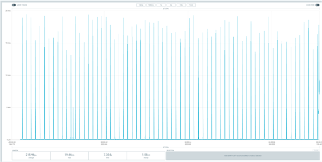
The same thing happens whenever we are running off the battery and try to connect a common gnd and vcc to use the digital pins available on the PPK2.
Is there something wrong with the way we are connecting the device, or is there something else we are missing that could be causing this?