This post is older than 2 years and might not be relevant anymore
More Info: Consider searching for newer posts

nRF52840 LFXO

I don't fully understand datasheet for LFXO.

17.4.3

CL_LFXO Load Capacitance = 12.5pF. Is this the recommended CL for external crystal?

RS_LXFO ESR = 100k. Is this the max ESR in crystal OR is this a ESR on the chip?

PD_LFXO = 1uW. Is this the recommended minimum Drive Level for crystal OR is this max outout power to crystal?

ILFXO = 0.23uA. Is this the current for silicon driving the crystal or is this the max output current to crystal?

I must be sure to not "overdrive" crystal. The crystals Drive Level I'm thinking of can be 0.1uW.

Kan anybody enlighten me because the datasheet it's not obvious to me.

  • Hi,

    To make sense of these specs please take a look at any 32MHz crystal datasheet.

    CL_LFXO Load Capacitance = 12.5pF. Is this the recommended CL for external crystal?

     This is the max recommended load capacitance given by the crystal datasheet (CL). To calculate the load capacitors value (the one connected to the crystal), C1 and C2 in our reference design, you should use the following formula:

    C1 = C2 = 2CL - C_pcb - C_pin

    CL: Load capacitance of the crystal (found in the crystal datasheet)

    C_pcb + C_pin is approximately 4 pF.

    As explained in General PCB design guidelines for nRRF52 blogpost.

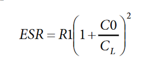
    RS_LXFO is the maximum equivalent series resistance, sometimes not given by the crystal manufacturer datasheet but can be calculated from:

    Where R1 is the motional resistance, C0 is the shunt or static capacitance of the crystal, and CL load capacitance of the crystal.

    So in summary, the values from the datasheet outline the maximum values for the values on the LFXO crystal specification/datasheet you choose.

    Best regards,

    Marjeris

  • It seems that the specification "talk's" about the recommended crystal, not driveability of the driver.

    I thought that PD_LXFO of 1uW is drive capability but maybe it's recommended DL of the crystal.

    I assume then that CL_LFXO, RS_LXFO and PD_LXFO is only recommendations to select a crystal...

    Reason for my question is that I have a crystal with DL of 0.5uW. I must be sure not to exceed 0.5uW. Best would be 0.1uW.

    One way is to select crystal with lower CL which gives lower current.

    I

  • Terho said:
    Reason for my question is that I have a crystal with DL of 0.5uW. I must be sure not to exceed 0.5uW. Best would be 0.1uW.

    Hi,

    You just have to make sure you don't exceed the maximum values. For the drive level, the maximum level the oscillator can drive the crystal is 0.5 µW. So the crystal must be able to handle at least this. If the crystal has a higher max tolerated drive strength, it can still be used with our chip.

    Best regards,

    Marjeris

  • Sorry but I looked in Product Specification v0.5.1. where PD_LXFO is 1uW. In v1.2 PD_LXFO is changed to 0.5uW.

    PD_LXFO is drive capability from oscillator to crystal and is 0.5uW.

    ILFXO (run current) is the current to oscillator (0.23uA). Is the current through crystal included in this?

    I guess if I select a crystal with "low" CL I can reduce DL lower than 0.5uW. And use crystal with DL 0.5uW max.

    Best Regards

    Terho

  • Hi,

    I am sorry for the late reply.

    Terho said:
    ILFXO (run current) is the current to oscillator (0.23uA). Is the current through crystal included in this?

    I_LFXO is the current that the oscillator draws from VDD. PD_LFXO  is the maximum level the oscillator can drive the crystal with. You need a crystal that can withstand at least 0.5uW, 0.1uW will be too little.

    Terho said:
    I guess if I select a crystal with "low" CL I can reduce DL lower than 0.5uW. And use crystal with DL 0.5uW max.

    This doesn't make sense. You need to find a crystal with > 0.5uW drive strength, if not you risk demaging the crystal.

    Best regards,

    Marjeris


Related