This post is older than 2 years and might not be relevant anymore
More Info: Consider searching for newer posts
This discussion has been locked.
You can no longer post new replies to this discussion. If you have a question you can start a new discussion

MCP2515 Library for NRF52

Hi everyone,

Im working and learning for private project CAN bus sniffer which when receive some data trigger some relay...

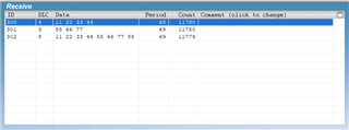
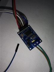
I have mcp2515_can hw-184 board on which Im replace TJA1050 chip for SN65HVD230. Im add J1 jumper to connect 120ohm resistor. Then Im connect on other side Lawicel CANUSB device together with CANHack software and open 500k CAN connection and periodicly send some data...

Im try few MCP2515 library written in C but looks like none of them do not work or maybe Im do something wrong... I don't have any special tool to analyze frequency on SPI interface...

I use in software:

SPI_SCK_PIN = P0.26

SPI_MISO_PIN  = P0.30

SPI_MOSI_PIN = P0.29

SPI_SS_PIN = P0.31

Connections:

MCP2515 <-> NRF52840 PDK

INT - No connection

SCK <-> P0.26

SI <-> P0.29

SO <-> P0.30

CS <-> P0.31

GND <-> GND

VCC <-> VDD

MCP2515:

NRF52840:

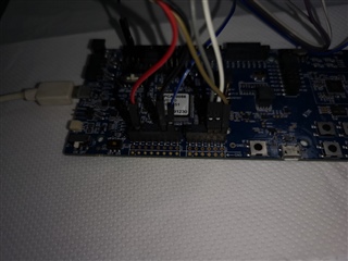
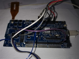
Any hint what to check that I will be sure that SPI interface and connections are ok and I have only software problems? Or is here some working MCP2515 library compatible with NRF5 SDK 17.0.2 ? Or maybe can I somehow change SPI example to test that MCP2515 realy work? I will and I use Softdevice S140(BLE peripheral) if this is important...

Thanks for any help.

Parents
  • Im little closer to complete CAN library... Now sending CAN messages are fixed and work normaly... In loop I send 3 different messages:

    uint8_t tmp_buffer0[4] = {0x11, 0x22, 0x33, 0x44};
    uint8_t tmp_buffer1[3] = {0x55, 0x66, 0x77};
    uint8_t tmp_buffer2[8] = {0x11, 0x22, 0x33, 0x44, 0x55, 0x66, 0x77, 0x88};

    mcp2515_write_canMsg(MCP_TXB0SIDH, 0x300, 0, 0, sizeof(tmp_buffer0), (uint8_t*)&tmp_buffer0);
    nrf_delay_ms(20);
    mcp2515_write_canMsg(MCP_TXB1SIDH, 0x301, 0, 0, sizeof(tmp_buffer1), (uint8_t*)&tmp_buffer1);
    nrf_delay_ms(20);
    mcp2515_write_canMsg(MCP_TXB2SIDH, 0x302, 0, 0, sizeof(tmp_buffer2), (uint8_t*)&tmp_buffer2);
    nrf_delay_ms(20);

    And data is received on end device:

    Now I need to implement CAN bus receive functions. I have think how to do it to save cpu cycles and think about two options:

    MCP2515 have INT output and it go low(0V) when data are received. On nrf52840 I set one GPIO as toggle and connect it to that pin.

    1.)
    When INT go down I set in gpio event bool variable to true and when INT go up(3,3V) I set that variable to false.
    In main loop I check that variable and if is TRUE then I check registers, read data and clear registers. Then gpio go UP and variable became FALSE...

    2.)
    When INT go down gpio event is triggered and I check registers, loop over registers, read data and clear registers. Here I need to do some repeated check because as I understand RX registers can be imediately filled with new data and gpio will not be toggled back to normal(Free registers) in that time...

    I think that for start I will go with option 1 to test and make functions for reading and parsing CAN data and then move to option 2 which will probably be more efficient...

Reply
  • Im little closer to complete CAN library... Now sending CAN messages are fixed and work normaly... In loop I send 3 different messages:

    uint8_t tmp_buffer0[4] = {0x11, 0x22, 0x33, 0x44};
    uint8_t tmp_buffer1[3] = {0x55, 0x66, 0x77};
    uint8_t tmp_buffer2[8] = {0x11, 0x22, 0x33, 0x44, 0x55, 0x66, 0x77, 0x88};

    mcp2515_write_canMsg(MCP_TXB0SIDH, 0x300, 0, 0, sizeof(tmp_buffer0), (uint8_t*)&tmp_buffer0);
    nrf_delay_ms(20);
    mcp2515_write_canMsg(MCP_TXB1SIDH, 0x301, 0, 0, sizeof(tmp_buffer1), (uint8_t*)&tmp_buffer1);
    nrf_delay_ms(20);
    mcp2515_write_canMsg(MCP_TXB2SIDH, 0x302, 0, 0, sizeof(tmp_buffer2), (uint8_t*)&tmp_buffer2);
    nrf_delay_ms(20);

    And data is received on end device:

    Now I need to implement CAN bus receive functions. I have think how to do it to save cpu cycles and think about two options:

    MCP2515 have INT output and it go low(0V) when data are received. On nrf52840 I set one GPIO as toggle and connect it to that pin.

    1.)
    When INT go down I set in gpio event bool variable to true and when INT go up(3,3V) I set that variable to false.
    In main loop I check that variable and if is TRUE then I check registers, read data and clear registers. Then gpio go UP and variable became FALSE...

    2.)
    When INT go down gpio event is triggered and I check registers, loop over registers, read data and clear registers. Here I need to do some repeated check because as I understand RX registers can be imediately filled with new data and gpio will not be toggled back to normal(Free registers) in that time...

    I think that for start I will go with option 1 to test and make functions for reading and parsing CAN data and then move to option 2 which will probably be more efficient...

Children
No Data
Related