This post is older than 2 years and might not be relevant anymore
More Info: Consider searching for newer posts

nRF52840 application won't completely run without power applied to VBUS

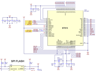
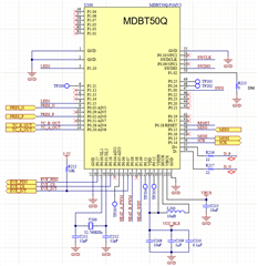
We've developed an application based on nRF52840 (via Raytac module MDBT50Q), utilizing the Adafruit Feather Express Bootloader as our basis to simplify the development.  Our application uses an external display driver with touch screen controller to interact with the user.

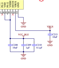
Our application runs and loads just fine while we have 5V power applied to VBUS (either from a USB connection, or directly connecting 5V).  Upon removing power to VBUS and powering on the rest of the board, we can blink LEDs but our display application won't load.  Our first circuit configuration was this, which matched one of the modes (or so we thought)

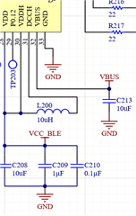
We thought maybe the lack of DCDC mode was the reason, so we updated the design to be:

And still no complete load of the application.  Since we can load a basic blinking led as well basic BLE and serial communications applications, I'm thinking it's something in their boot loader / our display driver code but I wanted to confirm the correct hardware configuration and make sure there weren't any configurations that we missed.  Ultimately the USB is used only to program the micro, but there are a handful of serial debug call we're making that won't need to be in the final product.  The micro circuit only needs 3.3V, but I do have 5V on the board for other purposes that I could power VBUS with.

We did happen to get a handful of boards that did not have the VDDH connection to VDD, but that did not seem to effect anything related to this issue. I have seen the other posts on that issue:

https://devzone.nordicsemi.com/f/nordic-q-a/44278/nrf52840-normally-supplied-via-vddh---can-it-be-supplied-just-via-vdd-for-swd-programming-without-connecting-vdd-and-vddh-together

devzone.nordicsemi.com/.../normal-mode-power-handling-of-vddh

Parents
  • Thanks for getting back to me.  Below should be the requested information.  For the most part the design is straight out of reference designs.

    Display Driver Circuit:

    Microcontroller:

    Both are powered by the same 3.3V supply, the micro having power through a ferrite bead.  No sequencing of power.

  • amaul said:
    Both are powered by the same 3.3V supply,

     Ok, so VBUS should not affect this ? Have you checked that it's 3.3V when VBUS is both connected and not connected?

    You control the display from the nRF52840 using SPI? Have you probed the lines, and checked if there is any difference when VBUS is both connected and not connected? e.g. what data is sent over SPI, and the voltage on the SPI lines

Reply
  • amaul said:
    Both are powered by the same 3.3V supply,

     Ok, so VBUS should not affect this ? Have you checked that it's 3.3V when VBUS is both connected and not connected?

    You control the display from the nRF52840 using SPI? Have you probed the lines, and checked if there is any difference when VBUS is both connected and not connected? e.g. what data is sent over SPI, and the voltage on the SPI lines

Children
  • Yeah that's where I'm at.  I have confirmed 3.3V using our onboard and external power supply.

    Yes, the display is controller over SPI.  I need to probe the lines to confirm, but I presume that would tell me there is an issue in the software, correct?  I have placed a delay in the code to reset the display driver well after the nordic chip boots but that did not fix the issue.

  • amaul said:
     I need to probe the lines to confirm, but I presume that would tell me there is an issue in the software, correct?

     Yes, most likely, i.e. SPI commands are not sent/received, but it could also indicate HW issues if there is a change in voltage level used for "logical 1"/"high level". You might want to check you firmware code as well, to see that you are not waiting for USBD events like APP_USBD_EVT_POWER_READY or APP_USBD_EVT_POWER_DETECTED before starting the display.

Related