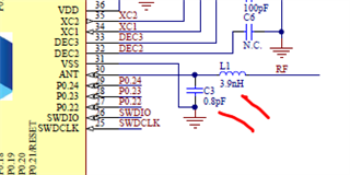
When I'm tuning the RF output (front end) of the nRF52832 to match 50 Ohm what state should the chip be in? Unprogrammed with power on or off? Or in receive mode with power on? This is with the VNA looking into the chip's RF output.
More specifically, these ref design components on a custom board
Hi Frank,
We usually don't use a VNA for tuning the radio matching network. It will only tell you the impedance when you look into the matching network but will not give you any information about the actual output power, level of harmonics or spurious in RX mode.
The matching network of the radio will be optimal in both RX and TX mode if the TX output power is maximized at the same times as the harmonics and the RX LO are minimized. When measuring output power and harmonics for TX we set the radio to send an unmodulated TX carrier and check the tuning for channels 02, 40 and 80. You can use the radio_test example for setting up the TX carrier.
We have a whitepaper on 'RF Performance Test Guidelines' you can take a look at for more information here.
A VNA is useful for antenna measurements. Keep in mind you need extra components to match the antenna, L1 and C3 are the matching components for the radio.
Best regards,
Marjeris
But how were the ref design values for C3 and L1 arrived at? Trial and error? There must be specific steps that were followed.
Hi,
Sorry for the late reply I didn't see you had a follow-up question before. I wouldn't call it trial and error. In general I can tell you the process for our customers usually consist of simulations in software to start with some values but there is always a part of the tuning process that need to be done manually.
We have a whitepaper that is a bit old but explains the process of tuning the radio matching network for one of our old chips (nRF24 series). It explains some of the logic back the iterations you will usually do to arrive to the right values for your design: https://infocenter.nordicsemi.com/pdf/nwp_013.pdf?cp=16_16
What I wanted to highlight with my previous answer is that instead of only looking at the impedance, it's better to tune for output power and harmonics. When you have the right output power and suppress the harmonics levels you will have the optimal performance for both RX and TX mode, and sometimes this will not be exactly 50 ohms, but close enough is OK. Even if you have a 75 ohms transmission line in a 50 ohm system the loss is only about 0.2dB due to mismatch.
In this answer here my colleague Ketil who did some measurements in the nRF52840 DK a while back explains that the impedance measured into the matching network of the nRF52840 in PCA10056 with the TX in +8dBm mode is actually closer to 70-80 ohms as this gives less harmonics: https://devzone.nordicsemi.com/f/nordic-q-a/72843/nrf52840-antenn-matching-and-micro-strip-characteristic-impedance/301212#301212
The impedance measured from the matching network in your design will again be different from this, since you need to tune for output power and harmonics in your own design, but the impedance will be correct as long as the output power is maximized at the same times as the harmonics and the RX LO are minimized.
If you need help with tuning your design for best performance we offer free of charge tuning for our customers, just open a private ticket if you want to request this service.
Best regards,
Marjeris
Thank you! The whitepaper is a great guide for what I'm trying to accomplish.