This post is older than 2 years and might not be relevant anymore
More Info: Consider searching for newer posts

Programm external board with 1.8V using nRF52840 DK

Hello Community,

I know there are already a few posts on this topic, but I wanted to make sure this is conform with my application.
I am trying to program an external board (with a nRF52840 chip) with the nRF52840 DK board, or with its J-linker.
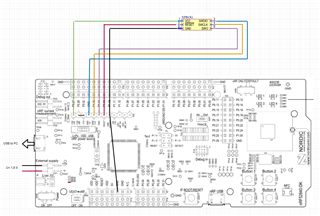
I have included my connection diagram as a picture below.
The external board runs completely on 1,8V. That's why the external supply of the DK should be used.
For this I have connected SB36.

Is the connection of the two boards correct?
Do I have to make any settings to be able to program only with 1.8V? (Hardware or Software)

Many thanks in advance.

  • Hi,

    Is there a specific reason for why you shorted SB36? It shouldn't be necessary, just make sure that you only supply one source at a time. The connection looks ok, just remember to supply the DUT externally with 1.8V.

    Do I have to make any settings to be able to program only with 1.8V? (Hardware or Software)

    regards

    Jared 

  • Hi Jared,

    Is there a specific reason for why you shorted SB36?

    I read this in a blog and looked it up in the SB configuration afterwards. I have pasted the excerpt from this below. I just want to make sure when I have the 5V applied to J2 via the USB and the 1.8V applied via P21, that I don't get an overvoltage at the components and they don't get damaged.

    With this configuration are all PIN's operated with 1.8V or are they still coupled to the 5V?

    DUT

    What do you mean by the DUT connection?

  • Hi,

    Shorting SB36 will override the reverse voltage protection and can in the worst case damage the board if you have connected more than one supply at a time. In your case specifically, since the DK will operate at a different voltage than your DUT (device under test) then I think it would be best to supply your board externally. Do not connect VDD_nRF to VCC on your board, instead connect VTG to VCC on your custom board, and the rest as you have shown in your sketch. 

    regards

    Jared

  • Hi Jared,

    I implemented your suggestion and powered my board with an external voltage source, which I also connected to GND Detect and VTG. I now get signals on the SWDCLK and SWDIO pins when I want to transmit something in Segger Studio.

    My problem is that the signals on these two pins are given out with a voltage of about 3.7V (max), but my board has only 1.8V. Can I set this directly on the J-Linker? Most J-Linkers support 1.2-5.5V, so this should be theoretically possible.
    Or do I need a external level shifter?


    greetings

  • Hi,

    I actually need to go back on what I said regarding programming at 1V8. The interface chip doesn't support.it after all. A level shifter might do the job but I haven't tested it myself, I think the best would be to just use an external programmer such as the SEGGER base EDU.

    I'm very sorry for the confusion. 

    best regards

    Jared 

Related