This post is older than 2 years and might not be relevant anymore
More Info: Consider searching for newer posts

Power consumption in the System Off mode for nRF52810

Hello. I'm researches the power consumption in System Off mode for nRF52810 chip. I use the next code to enter to System Off:

static void PrepareWakeUpPin (uint8_t pin_num, nrf_gpio_pin_sense_t pin_active)
{
    nrf_gpio_cfg_sense_input(pin_num, NRF_GPIO_PIN_PULLUP, pin_active);
}

/**
* Description:      This function is used to end active processes and enter the chip into System Off mode 
                    (Will be wake up only by Reset or Active state at SPI's CS pin).
* Input parameters: sleep_cause - Reason for going to sleep.
* Return perematers: none.
**/
void EnterToSleep (cause_of_sleep_t sleep_cause)
{
  switch (sleep_cause)
  {   
      case SLEEP_BY_SPI_CMD:  //If this function called from SPI handler - end all proccess and go to sleep
      {   
          ret_code_t err_code;
          
          NRF_LOG_FINAL_FLUSH();    //Flushing all log data from log queue before resseting/going to sleep

          SPI_Deinit();             //Deiniting SPI module to disable EasyDMA for success going to System Off mode (Sleep mode)
          
          BLE_Disable();

          bsp_board_leds_off();
        
          // Prepare wakeup pin.
          PrepareWakeUpPin(APP_SPIS_CS_PIN, NRF_GPIO_PIN_SENSE_LOW);  //Configure SPI chip select pin for wakeuping

          // Go to system-off mode (this function will not return; wakeup will cause a reset).
          err_code = sd_power_system_off();
          APP_ERROR_CHECK(err_code);     
      }
      case UNKNOWN_SLEEP_CAUSE:
      default:
        break;  
  }
}

Chip is goes to System Off and average consumption measured by UNI-T UT181A (UTM1181A) is about 0.2 μA (It's okay).

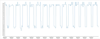
But, if you look at the consumption graph (recorded by UNI-T) in the System Off mode, then you can see current surges from 0.7 to 0.28 μA. What can they be caused by? And is it possible to drop the consumption down to 0.7μA?
Parents
  • Hi, here is a plot of the system OFF current on the nRF52810:

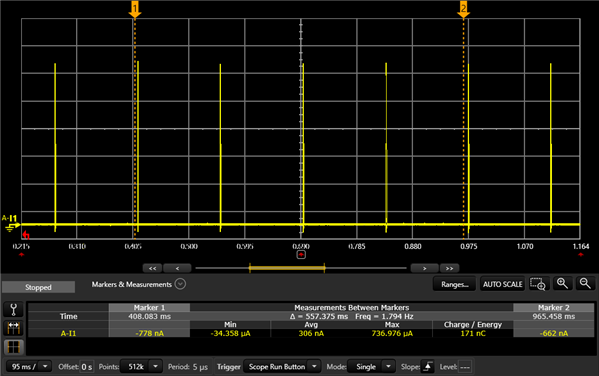
    As you can see the regulator operates in burst mode. The current between the spikes is in the 10-100 nA range, and the actual system OFF current is the average current including the bursts. The period between the spikes will be about 130 ms depending on the size of the DEC4 decoupling capacitor.

    It looks to me that the period in you plot is about 10 seconds, which does not fit into the actual system OFF current profile. So my theory is that what you are seeing in your plot is due to aliasing. During the higher levels in your plot the UNI-T captures the correct average current including the burst spikes, but as the time drifts the UNI-T eventually captures a series of low current samples (between the spikes), and then it repeats, giving you a 10 second period plot.

Reply
  • Hi, here is a plot of the system OFF current on the nRF52810:

    As you can see the regulator operates in burst mode. The current between the spikes is in the 10-100 nA range, and the actual system OFF current is the average current including the bursts. The period between the spikes will be about 130 ms depending on the size of the DEC4 decoupling capacitor.

    It looks to me that the period in you plot is about 10 seconds, which does not fit into the actual system OFF current profile. So my theory is that what you are seeing in your plot is due to aliasing. During the higher levels in your plot the UNI-T captures the correct average current including the burst spikes, but as the time drifts the UNI-T eventually captures a series of low current samples (between the spikes), and then it repeats, giving you a 10 second period plot.

Children
No Data
Related