This post is older than 2 years and might not be relevant anymore
More Info: Consider searching for newer posts

nRFX based PDM to PCM implementation (I2S example)

Hello,

I am currently interfacing my nRF52840 DK with i2S based MP34DT05 sensor. I am using nrfx i2s driver's for interfacing with sensor. I am using master clk of 2MHz, LCLK 16KHZ. 

My sensor output PDM data. In my project I am recording audio samples on left channel, so I am currently getting 2*16bit of left data per 32bits as shown in nrf docs. I have got 16bit recorded samples in buffer, but to how to convert this pdm data in pcm format. 

Normally we need to divide the PDM data with a decimation factor, but in I2S we already are dividing the bit sampling rate with ratio value. So is the output from the I2S itself is decimated PCM ?  

Or can anyone give a example of how to convert the PDM to PCM data. Any sort of help is dually appreciated. 

Parents
No Data
Reply
  • I am currently using ncs(latest), for interfacing PDM based sensor with nRF52840 DK .Okay this the implementation code i tried using nrfx pdm drivers, but without any success. I have reffered various forum post to implement this. 

    Firstly i am running PDM in default configuration as you see in my code. The clock frequency is set around 1MHz with Ratio of 64x which gives around 16K samples/sec.

    /*
     * Copyright (c) 2020 BayLibre, SAS
     *
     * SPDX-License-Identifier: Apache-2.0
     */
    
    #include <zephyr.h>
    #include <stdio.h>
    #include <nrfx_pdm.h>
    
    #include <string.h>
    #include <stdlib.h>
    #include <stdint.h>
    
    #define PDM_BUF_SIZE 1024  //length of buffer in 16 bit words
    #define PDM_CLK_PIN                     36// 32+4 = p1.04
    #define PDM_DIN_PIN                     37// 32+5 = p1.05
    
    uint16_t pdm_buf[PDM_BUF_SIZE];
    
    static bool data_ready_flag = false;
    int8_t counter=0;
    bool write_data = false;


    void nrfx_pdm_event_handler(nrfx_pdm_evt_t const * const p_evt)
    {
        if(p_evt->buffer_requested)
        {
           nrfx_pdm_buffer_set(pdm_buf, PDM_BUF_SIZE);
        }
        if(p_evt->buffer_released != 0)
        {
          write_data = true;
           //printf("Out: %.2x %.2x\r\n", (uint16_t)pdm_buf[0], (uint16_t)pdm_buf[1]);
        }
    }
    
    /*ISR workaround given by Nordic*/
    ISR_DIRECT_DECLARE(pdm_isr_handler)
    {
      nrfx_pdm_irq_handler();
      ISR_DIRECT_PM(); /* PM done after servicing interrupt for best latency
                        */
      return 1; /* We should check if scheduling decision should be made */
    }
    
    
    void main(void)
    {
        nrfx_err_t ret = NRFX_SUCCESS;
    
        IRQ_DIRECT_CONNECT(PDM_IRQn, 0, pdm_isr_handler, 0);  //workaround line 
    
        nrfx_pdm_config_t pdm_config = NRFX_PDM_DEFAULT_CONFIG(PDM_CLK_PIN, PDM_DIN_PIN); /*configures CLK to pin 10 and Din to pin 11*/
    /*
        pdm_config.clock_freq = NRF_PDM_FREQ_1280K;
        pdm_config.ratio = NRF_PDM_RATIO_80X;
        pdm_config.edge = NRF_PDM_EDGE_LEFTRISING;
        pdm_config.gain_l = NRF_PDM_GAIN_MAXIMUM;
        pdm_config.gain_r = NRF_PDM_GAIN_MAXIMUM;
    */
    
        ret = nrfx_pdm_init(&pdm_config, nrfx_pdm_event_handler);
        if(ret != NRFX_SUCCESS){
          printk("PDM Init succesfull.\r\n");
        }
    
        ret = nrfx_pdm_start();
        if(ret != NRFX_SUCCESS)
        {
          printk("PDM recording started succesfully\r\n");
        }
    
      
      while(1)
      {
        while(!write_data){
          k_sleep(K_MSEC(100));
        }
    
        ret = nrfx_pdm_stop();
        if(ret != NRFX_SUCCESS){
          printk("Error Init\r\n");
        }
    
    
        printk("%4x is current value at %x\n", pdm_buf[0], &pdm_buf);
      }


    }
    

    I have a doubt here, shouldn't the output from sensor be 1MHz, which is than sampled by nRF52840 PDM peripheral by 64x ? 

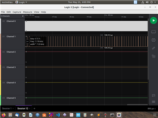
    Because when i connect my logic analyzer on CLK pin and DIN pin nRF52840 board, CLK  is 1MHz freq., but the output seen on DIN pin is just around 7KHz frquency. 

    Below is the image for the refference:

    Now when i use the configurations that's commented in the above code,

        pdm_config.clock_freq = NRF_PDM_FREQ_1280K;
        pdm_config.ratio = NRF_PDM_RATIO_80X;
        pdm_config.edge = NRF_PDM_EDGE_LEFTRISING;
        pdm_config.gain_l = NRF_PDM_GAIN_MAXIMUM;
        pdm_config.gain_r = NRF_PDM_GAIN_MAXIMUM;
    

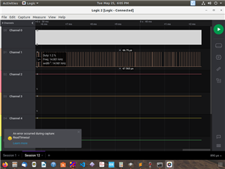
    I get CLK freq= 1.2 MHz and DIN frequency around 14-16KHz. Now again my question is shouldn't my DIN frquency from the sensor PDM output  be 1MHz instead of jutst 16KHz ? which than get sampled by PDM interface at nRF52840 side. 

    Can anyone tell me whats the issue here ? Or any guidance for the same is appreciated.

Children
  • Hello,

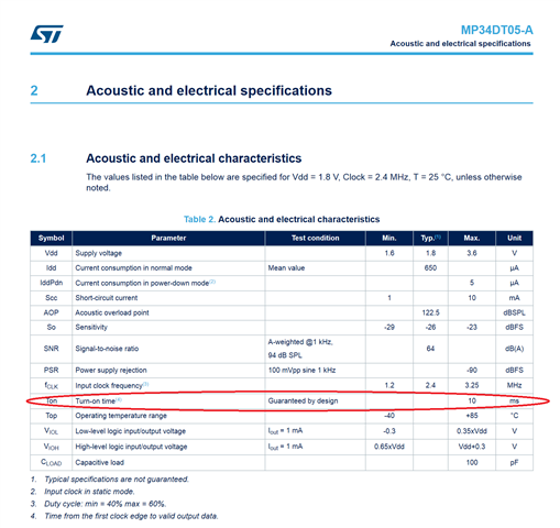
    first off, I would recommend printing out the entire pdm_buf array and look at the contents. The microphone has a ~10 ms startup time (see below), so it is likely that the first sample in the first buffer will always be the same value.

    Second, data on the DIN pin is normally in the same frequency range as the clock signal, but this will vary according to the acoustic input to the sensor.

    If you want to validate the DIN signal you see in the logic analyzer, you can try the attached python script. The script parses and filters an exported .csv from Saleae Logic analyzer software. Just make sure the exported csv has DIN as the first exported value. For example:

    Time [s],Channel 5,Channel 7
    -0.000051150,0,0
    0.000000000,1,0
    0.000000030,1,1
    0.000999980,0,1
    0.001000018,0,0
    0.001999976,1,0
    0.002000010,1,1
    0.002999954,0,1
    0.002999998,0,0

    Here, channel 5 is DIN, and Channel 7 is CLK.

    Python script syntax, using 16 kHz as target PCM rate:

    $ python pdm_parse.py my_exported_saleae_capture.csv 16000

    import sys,os,re
    import numpy as np
    import scipy.io.wavfile as wf
    from scipy import signal
    
    #fname = 'pdm.csv'
    #Fs    = 16000
    
    if len(sys.argv) < 3:
        print('usage: {} input.csv Fs'.format(sys.argv[0]))
        exit(-1)
        
    fname = sys.argv[1]
    Fs    = int(sys.argv[2])
    
    print('File: {}'.format(fname))
    print('Fs:   {}'.format(Fs))
    
    pattern         = re.compile(r'[-/.0-9]*,[ ]*([0-1]{1}),[ ]*([0-1]{1})')
    bitstream_right = []
    bitstream_left  = []
    
    print('Note: Make sure PDM DATA is before PDM CLK in trace')
    
    with open(fname, 'rb') as fin:
        prev_clk = None
    
        for line in fin:
            try:
                data, clk = re.findall(pattern, line.decode('utf-8'))[0]
            except:
                continue
    
            if prev_clk == '1' and clk == '0':
                # Falling clock edge
                if data == '1':
                    bitstream_right.append(32767)
                else:
                    bitstream_right.append(-32767)
            elif prev_clk == '0' and clk == '1':
                # Rising clock edge
                if data == '1':
                    bitstream_left.append(32767)
                else:
                    bitstream_left.append(-32767)
    
            prev_clk = clk
    
    
    print('Found {} samples in right bitstream'.format(len(bitstream_right)))
    print('Found {} samples in left bitstream'.format(len(bitstream_left)))
    
    y_right = signal.decimate(bitstream_right, 80, ftype='fir')
    y_left  = signal.decimate(bitstream_left, 80, ftype='fir')
    
    wf.write(re.sub(r'\.[\w]+$', '_left.wav', fname), Fs, y_left.astype(np.int16))
    wf.write(re.sub(r'\.[\w]+$', '_right.wav', fname), Fs, y_right.astype(np.int16))

Related