This post is older than 2 years and might not be relevant anymore
More Info: Consider searching for newer posts

nRFX based PDM to PCM implementation (I2S example)

Hello,

I am currently interfacing my nRF52840 DK with i2S based MP34DT05 sensor. I am using nrfx i2s driver's for interfacing with sensor. I am using master clk of 2MHz, LCLK 16KHZ. 

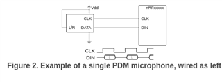
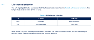
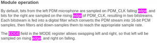
My sensor output PDM data. In my project I am recording audio samples on left channel, so I am currently getting 2*16bit of left data per 32bits as shown in nrf docs. I have got 16bit recorded samples in buffer, but to how to convert this pdm data in pcm format. 

Normally we need to divide the PDM data with a decimation factor, but in I2S we already are dividing the bit sampling rate with ratio value. So is the output from the I2S itself is decimated PCM ?  

Or can anyone give a example of how to convert the PDM to PCM data. Any sort of help is dually appreciated. 

Parents
No Data
Reply
  • Did you try running the python script on this measurement?

    Hello, i tried running python script on measurement and i can just hear noise. I have attached the sample .wav in my previous reply, where you can literally hear noise only.

    Note: Below .wav are generated by above give analyzer output from sensor. Just noise.

    What does your test setup look like? Are you powering the sensor from one of the nRF52840-DK headers, or is there a separate supply? Are there other components connected to the CLK or DIN lines?

    I am giving supply to DK via nRF USB. I am giving power supply from nRF52840 connectors VDD to MP34DT05 Vcc and GND to GND and rest connections are mentioned below. And the CLK and DIN pins are just connected to sensor as shown below.

    MP34DT05 Sensor connection to  nRF52840DK

      CLK    -  P1.04 (header)

      DOUT -  P1.05 (header)

      L/R     -  Not connected (as datasheet says "As the L/R pin is internally connected to GND via a 200 kohm pull/down resistor, it is not mandatory to connect the pin itself to GND for the respective channel selection.")

    L/R pin connection Information

    When i see the nRF52840 PDM docs (Fig 2), it shows i have to connect L/R pin to VDD for left channel, but my sensor say opposite. 

    nRF52840 PDM Doc

    Sensor Doc:

    By referring the below given timing diagram from datasheet and the nRF52840 pdm doc, i have set the  " pdm_config.edge = NRF_PDM_EDGE_LEFTRISING" in my code as left channel is sampled on Rising edge.

    Sensor Datasheet Timing Diag.

    From nRF52840 DK docs

    For more reference here is the datasheet of sensor MP34DT05 sensor:

    mp34dt05-a.pdf

    I would recommend connecting the CLK signal to the sensor, but keep the DIN line to nRF52840 disconnected.

    Okay will also check that and will also use python script on the same. Any others suggestions or guidance is also appreciated.

Children
No Data
Related