This post is older than 2 years and might not be relevant anymore
More Info: Consider searching for newer posts

nRFX based PDM to PCM implementation (I2S example)

Hello,

I am currently interfacing my nRF52840 DK with i2S based MP34DT05 sensor. I am using nrfx i2s driver's for interfacing with sensor. I am using master clk of 2MHz, LCLK 16KHZ. 

My sensor output PDM data. In my project I am recording audio samples on left channel, so I am currently getting 2*16bit of left data per 32bits as shown in nrf docs. I have got 16bit recorded samples in buffer, but to how to convert this pdm data in pcm format. 

Normally we need to divide the PDM data with a decimation factor, but in I2S we already are dividing the bit sampling rate with ratio value. So is the output from the I2S itself is decimated PCM ?  

Or can anyone give a example of how to convert the PDM to PCM data. Any sort of help is dually appreciated. 

  • Sorry, I have been thinking about this one for a bit, and I don't have any good ideas. I checked if it could be a VDD supply issue regarding nRF_USB, but I don't think that is a problem. VDD on the headers should be able to supply external circuitry regardless of which USB connection you have used.

    I think it would be worthwhile to test another sensor, in case this particular unit is faulty.

    To summarize: You've verified that VDD and CLK is within the sensor specification (albeit in the lower end for the clock, but that should not matter), but still the output does not look good. You've also verified that there is no external circuitry messing with the output signal, by disconnecting the data line. I think the next step would be to try another sensor unit.

  • Hello,

    there are a couple of problems with the script and data:
    1) wavfile.writeframes() needs raw int16_t byte data, not a string. Your read the text file as a string, but to put it in writeframes each of the values in the comma-separated string needs to be extracted and formatted into a continuous array of formatted bytes.

    2) The first parameter (number of channels) in wavfile.setparams is 2, but the data seems to be single channel? How is the PDM peripheral configured in the code?

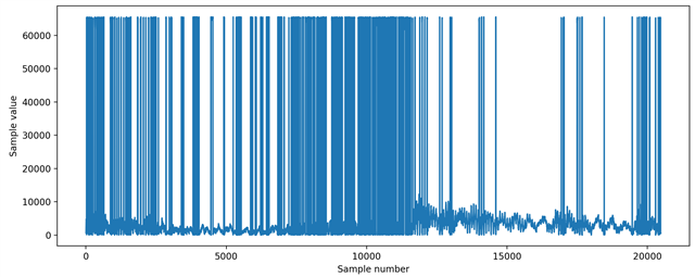
    3) I would recommend printing your buffer as int16_t (signed short), as this is the PCM format generated by the PDM peripheral. When I plot the data it looks somewhat good, but there also seems to be some formatting error going on in the printouts:

  • This seems to work better. Tested using python3.

    import sys
    import wave
    import re
    import struct
    
    with open('0317.test.txt', 'r') as pcmfile:
        # Convert comma-separated hex strings into list of integers
        pcm_list = list(map(lambda x: int(x, 16), re.findall(r'([\w\d]+)', pcmfile.read())))
    
    # Convert list of integers into little endian-encoded byte array
    pcmdata = bytes()
        
    for sample in pcm_list:
        # Original sample is signed 16-bit. Format as uint16, and decode as int16.
        tmpdata = struct.pack('<H', sample)
        tmpdata = struct.unpack('<h', tmpdata)[0]
        pcmdata += struct.pack('<h', tmpdata)
        
    with wave.open('0317.test.wav', 'wb') as wavfile:
        wavfile.setparams((1, 2, 16000, 0, 'NONE', 'NONE'))
        wavfile.writeframes(pcmdata)

  • The UART baud rate might be an issue here. The default is 115200 baud, while your audio is 16-bit * 16 kHz = 256000. To test if this is the problem, you can try setting the board baud rate to 1000000 instead of 115200. The proper way to do this is to set up an overlay file in your sample, but as a quick test you can also update this config: https://github.com/nrfconnect/sdk-zephyr/blob/master/boards/arm/nrf52840dk_nrf52840/nrf52840dk_nrf52840.dts#L146

    I also recommend checking out the USBD audio sample: https://github.com/nrfconnect/sdk-zephyr/tree/master/samples/subsys/usb/audio/headset This sample makes the nRF52840-DK appear as an audio device when connected to a USB host. With this you could copy the audio from the PDM directly to USB, and listen to the audio in real time on your computer without any additional scripts.

  • If you find any bug in above code kindly mention or have any another tricks than please help because i can't recognize voice patterns just on the basis of 2-3 sec audio.

    I think it would make things easier if you use some data structures to help organize the PCM buffers. Specifically, I recommend using a memory slab for allocating PCM buffers, and a queue/FIFO to enqueue PCM buffers that have been filled.

    Let's say your algorithm runs on audio block sizes of 100 milliseconds, at 16 kHz sampling rate, this means each audio block is 3200 bytes. You would then define a memory slab of size X * 3200. X can be any number that fits within total memory. Note that it is probably best to define a struct for your audio data, which contains the int16_t audio buffer, plus the fifo_reserved data field, plus whatever else might be useful.

    In the PDM event hander, when a new buffer is requested, you try to allocate a new buffer from the slab (k_mem_slab_alloc). If this fails, you can log the error.

    In the PDM event handler, when a freshly filled buffer is released, you put the pointer to this buffer in the FIFO (k_fifo_put).

    Your algorithm can run as soon as there is one or more items in the FIFO (k_fifo_get).

    Once the algorithm has finished processing one audio buffer, it will release it back to the memory slab (k_mem_slab_free).

    This way your algorithm will always process the audio in order, and it is easy to see if you have a bottleneck somewhere.

    If you have multiple consumers of your audio data (e.g. local algorithm plus UART printout), this can be solved by adding a reference counter to the audio buffer struct.

Related