This post is older than 2 years and might not be relevant anymore
More Info: Consider searching for newer posts

nRFX based PDM to PCM implementation (I2S example)

Hello,

I am currently interfacing my nRF52840 DK with i2S based MP34DT05 sensor. I am using nrfx i2s driver's for interfacing with sensor. I am using master clk of 2MHz, LCLK 16KHZ. 

My sensor output PDM data. In my project I am recording audio samples on left channel, so I am currently getting 2*16bit of left data per 32bits as shown in nrf docs. I have got 16bit recorded samples in buffer, but to how to convert this pdm data in pcm format. 

Normally we need to divide the PDM data with a decimation factor, but in I2S we already are dividing the bit sampling rate with ratio value. So is the output from the I2S itself is decimated PCM ?  

Or can anyone give a example of how to convert the PDM to PCM data. Any sort of help is dually appreciated. 

  • Hello,

    instead of the NRFX I2S driver, it sounds like you should use the NRFX PDM driver: https://infocenter.nordicsemi.com/topic/sdk_nrf5_v17.0.2/group__nrf__pdm.html

    The PDM driver interfaces with the PDM hardware on nRF52840: https://infocenter.nordicsemi.com/topic/ps_nrf52840/pdm.html?cp=4_0_0_5_14

    The PDM hardware has the decimation filtering built into hardware, and outputs PCM samples. Two decimation factors are supported, 64 and 80. For example, if you want a 16 kHz PCM rate, you should choose a PDM clock rate of 1.28 MHz, and a decimation factor of 80.

    Best regards,

    Audun

  • Hello,

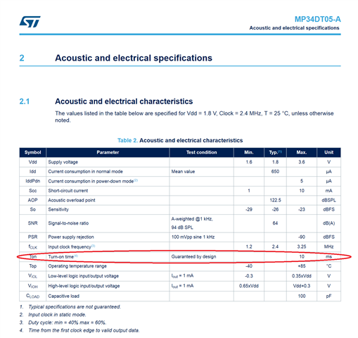
    first off, I would recommend printing out the entire pdm_buf array and look at the contents. The microphone has a ~10 ms startup time (see below), so it is likely that the first sample in the first buffer will always be the same value.

    Second, data on the DIN pin is normally in the same frequency range as the clock signal, but this will vary according to the acoustic input to the sensor.

    If you want to validate the DIN signal you see in the logic analyzer, you can try the attached python script. The script parses and filters an exported .csv from Saleae Logic analyzer software. Just make sure the exported csv has DIN as the first exported value. For example:

    Time [s],Channel 5,Channel 7
    -0.000051150,0,0
    0.000000000,1,0
    0.000000030,1,1
    0.000999980,0,1
    0.001000018,0,0
    0.001999976,1,0
    0.002000010,1,1
    0.002999954,0,1
    0.002999998,0,0

    Here, channel 5 is DIN, and Channel 7 is CLK.

    Python script syntax, using 16 kHz as target PCM rate:

    $ python pdm_parse.py my_exported_saleae_capture.csv 16000

    import sys,os,re
    import numpy as np
    import scipy.io.wavfile as wf
    from scipy import signal
    
    #fname = 'pdm.csv'
    #Fs    = 16000
    
    if len(sys.argv) < 3:
        print('usage: {} input.csv Fs'.format(sys.argv[0]))
        exit(-1)
        
    fname = sys.argv[1]
    Fs    = int(sys.argv[2])
    
    print('File: {}'.format(fname))
    print('Fs:   {}'.format(Fs))
    
    pattern         = re.compile(r'[-/.0-9]*,[ ]*([0-1]{1}),[ ]*([0-1]{1})')
    bitstream_right = []
    bitstream_left  = []
    
    print('Note: Make sure PDM DATA is before PDM CLK in trace')
    
    with open(fname, 'rb') as fin:
        prev_clk = None
    
        for line in fin:
            try:
                data, clk = re.findall(pattern, line.decode('utf-8'))[0]
            except:
                continue
    
            if prev_clk == '1' and clk == '0':
                # Falling clock edge
                if data == '1':
                    bitstream_right.append(32767)
                else:
                    bitstream_right.append(-32767)
            elif prev_clk == '0' and clk == '1':
                # Rising clock edge
                if data == '1':
                    bitstream_left.append(32767)
                else:
                    bitstream_left.append(-32767)
    
            prev_clk = clk
    
    
    print('Found {} samples in right bitstream'.format(len(bitstream_right)))
    print('Found {} samples in left bitstream'.format(len(bitstream_left)))
    
    y_right = signal.decimate(bitstream_right, 80, ftype='fir')
    y_left  = signal.decimate(bitstream_left, 80, ftype='fir')
    
    wf.write(re.sub(r'\.[\w]+$', '_left.wav', fname), Fs, y_left.astype(np.int16))
    wf.write(re.sub(r'\.[\w]+$', '_right.wav', fname), Fs, y_right.astype(np.int16))

  • Thanks for the Logic analyzer traces!

    The logic analyzer trace from the sensor directly looks to be more in range of the expected frequency, but it's hard to say if it's good or not just by looking at this snippet. Did you try running the python script on this measurement?

    It's possible that the issue is electrical. What does your test setup look like? Are you powering the sensor from one of the nRF52840-DK headers, or is there a separate supply? Are there other components connected to the CLK or DIN lines?

    I would recommend connecting the CLK signal to the sensor, but keep the DIN line to nRF52840 disconnected. This way you can measure the data output on the sensor again, without getting potential interference from the nRF52840-DK. For example if the nRF52840 is configured with a pull resistor on P1.05, this could influence the signal level.

  • L/R pin connection Information

    When i see the nRF52840 PDM docs (Fig 2), it shows i have to connect L/R pin to VDD for left channel, but my sensor say opposite. 

    I wouldn't worry so much about the L/R selection or clock edge details at this stage. In my experience when only one microphone is connected to the PDM peripheral, the data signal will in effect end up in both channels as no other sensor is driving the data line for the other channel. Regardless, you can configure the nrfx pdm driver to sample stereo and sort out the exact channel details later.

    Your hardware setup sounds sensible. The MP34DT05 supply voltage falls within VDD on the nRF52840-DK. I think VDD on nRF52840-DK defaults to 1.8V, but I'm not 100% sure.

    Okay will also check that and will also use python script on the same. Any others suggestions or guidance is also appreciated.

    In terms of electrical setup, wire length could be an issue.

    In the logic analyzer trace made at the sensor, I also noticed that the two signals seems very similar. It's hard to tell from just this snippet, but could there be a short between the clock and data lines?

    This screenshot below was taken a while ago, but shows the kind of pattern I would expect to see on the PDM clock and data lines:

  • Can it be a problem with my sensor ? It is outputting at PDM CLK rate but false data.  

    It's possible. If you have another sensor at hand, it would be worth checking.

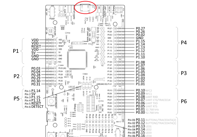
    I re-read your description the setup. Am I understanding correctly that you don't have this USB connected?

    Have you measured the voltage on the sensor VDD?

Related