This post is older than 2 years and might not be relevant anymore
More Info: Consider searching for newer posts

Error when using TIMER with nrf_drv_timer.h

Hi,

I am trying to generate a 1 MHz clock in the nRF52832 (nRF52 DK). This is my code:

static const nrf_drv_timer_t TIMER_LED = NRF_DRV_TIMER_INSTANCE(2);

void timer_led_event_handler(nrf_timer_event_t event_type, void* p_context) {
    switch (event_type) {
        case NRF_TIMER_EVENT_COMPARE0:
            nrf_gpio_pin_toggle(PIN_SIPOCLK);
            bsp_board_led_invert(BSP_BOARD_LED_0);
            break;

        default:
            //Do nothing.
            break;
    }
}

void timer_init(void) {
    uint32_t time_ms = 500; //Time(in miliseconds) between consecutive compare events.
    uint32_t time_ticks;
    ret_code_t err_code;

    nrf_drv_timer_config_t timer_cfg = NRF_DRV_TIMER_DEFAULT_CONFIG;
    err_code = nrf_drv_timer_init(&TIMER_LED, &timer_cfg, timer_led_event_handler);
    APP_ERROR_CHECK(err_code);
    
    time_ticks = nrf_drv_timer_ms_to_ticks(&TIMER_LED, time_ms);
    nrf_drv_timer_extended_compare(&TIMER_LED,
                                NRF_TIMER_CC_CHANNEL0,
                                time_ticks,
                                NRF_TIMER_SHORT_COMPARE0_CLEAR_MASK,
                                true);
    nrf_drv_timer_enable(&TIMER_LED);
}

// Main.
int main(void) {
    timer_init();
    
    while (true) {
            // Do nothing
    }
}

When I try to build, I get numerous errors like this

error: 'NRFX_TIMER2_INST_IDX' undeclared here (not in a function); did you mean 'NRFX_TIMER_INSTANCE'?


I think that nrfx_timer.h is a newer library that nrf_drv_timer.h. However, I am using the timer example of SDK 17.0.2 for developing this. Why am I getting this errors?

Thanks in advanced.
Parents
  • Hi,

    The nrf_drv use the nrfx implementation under the hood, which is why you see this. The reason for this exact error is probably that you have not enabled TIMER2 in sdk_config.h. Specifically, you should ensure that TIMER2_ENABLED is set to 1 in your sdk_config.h, as well as TIMER_ENABLED.

  • I managed to get TIMER working. Now, I want to implement both the TIMER and UART. I have successfully implemented UART with calls to uart_event_handle(). However, when I try to implement both the UART and the TIMER (generating a 250 kHz clock in a GPIO), UART's callback is never reached. Is there any conflict between TIMER and UART?

  • Hi,

    The TIMER and UART peripheral are independent, so I cannot see any conflicts in HW. I suspect something related to your SW (I cannot say wat without knowing more).

  • Hi,

    It is a simple implementation in which I receive 35 bytes of data from UART and a 250 kHz is ticking. I attach here the code. Thanks in advanced.

    // ------------------------------------------------------------------------------------------------
    // INCLUDES
    
    #include <stdbool.h>
    #include <stdint.h>
    #include <stdio.h>
    #include "app_uart.h"
    #include "app_error.h"
    #include "bsp.h"
    #include "boards.h"
    #include "nrf.h"
    #include "nrf_drv_timer.h"
    #include "nrf_uart.h"
    #include "nrf_gpio.h"
    
    // ------------------------------------------------------------------------------------------------
    // VARIABLES AND CONSTANTS
    
    #define UART_TX_BUF_SIZE        256                         /**< UART TX buffer size. */
    #define UART_RX_BUF_SIZE        256                         /**< UART RX buffer size. */
    #define UART_HWFC               APP_UART_FLOW_CONTROL_DISABLED
    #define PIN_SIPOCLK             NRF_GPIO_PIN_MAP(0, 16)
    #define NBYTES                  35
    
    const nrf_drv_timer_t TIMER_LED = NRF_DRV_TIMER_INSTANCE(2);
    uint8_t i = 0;
    bool clkLevel = false;
    uint8_t word[NBYTES];
    uint8_t cr;
    
    // ------------------------------------------------------------------------------------------------
    // FUNCTION DECLARATIONS
    
    void gpio_init(void);
    void uart_init(void);
    void uart_event_handle(app_uart_evt_t * p_event);
    void timer_init(void);
    void timer_led_event_handler(nrf_timer_event_t event_type, void* p_context);
    
    // ------------------------------------------------------------------------------------------------
    // MAIN FUNCTION
    
    int main(void) {
        bsp_board_init(BSP_INIT_LEDS);
        gpio_init();
        uart_init();
        timer_init();
    
        while (true) {      
        }
    }
    
    // ------------------------------------------------------------------------------------------------
    // OTHER FUNCTIONS
    
    /*
        GPIO initilization
    */
    void gpio_init(void) {
        nrf_gpio_cfg_output(PIN_SIPOCLK);
        nrf_gpio_pin_clear(PIN_SIPOCLK);
    }
    
    // UART initialization.
    void uart_init(void) {
        uint32_t err_code;
    
        const app_uart_comm_params_t comm_params = {
              RX_PIN_NUMBER,
              TX_PIN_NUMBER,
              RTS_PIN_NUMBER,
              CTS_PIN_NUMBER,
              UART_HWFC,
              false,
              NRF_UART_BAUDRATE_115200
        };
    
        APP_UART_FIFO_INIT(&comm_params,
                            UART_RX_BUF_SIZE,
                            UART_TX_BUF_SIZE,
                            uart_event_handle,
                            APP_IRQ_PRIORITY_LOWEST,
                            err_code);
    
        APP_ERROR_CHECK(err_code);
    }
    
    // Handler for storing NBYTES bytes of data received over UART.
    void uart_event_handle(app_uart_evt_t * p_event) {
        switch (p_event->evt_type) {
          case APP_UART_DATA_READY:
              app_uart_get(&cr);
              word[i] = cr;
    
              if (i == NBYTES-1) {
                  i = 0;
              } else {
                  i = i + 1;
              }    
                
              break;
    
          case APP_UART_COMMUNICATION_ERROR:
              APP_ERROR_HANDLER(p_event->data.error_communication);
              break;
    
          case APP_UART_FIFO_ERROR:
              APP_ERROR_HANDLER(p_event->data.error_code);
              break;
    
          default:
              break;
        }
    }
    
    
    void timer_init(void) {
        uint32_t time_us = 4;     
        uint32_t time_ticks;
        ret_code_t err_code;
    
        nrf_drv_timer_config_t timer_cfg = NRF_DRV_TIMER_DEFAULT_CONFIG;
        timer_cfg.frequency = NRF_TIMER_FREQ_16MHz;
        err_code = nrf_drv_timer_init(&TIMER_LED, &timer_cfg, timer_led_event_handler);
        APP_ERROR_CHECK(err_code);
        
        time_ticks = nrf_drv_timer_us_to_ticks(&TIMER_LED, time_us);
        nrf_drv_timer_extended_compare(&TIMER_LED,
                                    NRF_TIMER_CC_CHANNEL0,
                                    time_ticks,
                                    NRF_TIMER_SHORT_COMPARE0_CLEAR_MASK,
                                    true);
        nrf_drv_timer_enable(&TIMER_LED);
    }
    
    
    // Timer handler.
    void timer_led_event_handler(nrf_timer_event_t event_type, void* p_context) {
            
        switch (event_type) {
            case NRF_TIMER_EVENT_COMPARE0:
                if (clkLevel == false) {
                    nrf_gpio_pin_set(PIN_SIPOCLK);
                    clkLevel = true;
                } else {
                    nrf_gpio_pin_clear(PIN_SIPOCLK);
                    clkLevel = false;                                    
                }
    
                break;
    
            default:
             
                break;
        }       
    }

  • Hi,

    I do not see any conflict here but you have a very high frequency of the timer interrupts, so if the timer has higher priority than your UART then that could cause problems. If all you need to do with the timer is to generate the 250 kHz clock then you should do that by connecting the timer to GPIOTE via PPI instead of doing it in firmware. That way no CPU is needed except for configuration.

Reply Children
  • Hi,

    I just tried the code with a 1 ms timer and everything works fine. Is there any example or doc in the SDK for connecting the timer to GPIOTE via PPI?

  • I found the GPIOTE example in the SDK. With TIMER+GPIOTE via PPI I can obtain a ~200 kHz clock but I would like to reach 1 MHz. Is this possible? Besides generating the clock, I want to handle a couple more GPIO at that frequency

  • The sdk_config.h file in the GPIOTE example has set TIMER_DEFAULT_CONFIG_FREQUENCY to 4, which uses the prescaler to make the timer frequency 1 MHz. To output 1 Mhz you much have a higher TIMER frequency, so set it to 0 to make the timer 16 MHz (no prescaler).

    Then use an appropriate value for the compare register. By using 8 and a 16 MHz timer, the output will toggle at 1 MHz.

    Specifically, these are the two small changes needed:

    diff --git a/examples/peripheral/gpiote/main.c b/examples/peripheral/gpiote/main.c
    index 31b2c3a..762fd69 100644
    --- a/examples/peripheral/gpiote/main.c
    +++ b/examples/peripheral/gpiote/main.c
    @@ -81,7 +81,7 @@ static void led_blinking_setup()
         APP_ERROR_CHECK(err_code);
    
    
    -    nrf_drv_timer_extended_compare(&timer, (nrf_timer_cc_channel_t)0, 200 * 1000UL, NRF_TIMER_SHORT_COMPARE0_CLEAR_MASK, false);
    +    nrf_drv_timer_extended_compare(&timer, (nrf_timer_cc_channel_t)0, 8, NRF_TIMER_SHORT_COMPARE0_CLEAR_MASK, false);
    
         err_code = nrf_drv_ppi_channel_alloc(&ppi_channel);
         APP_ERROR_CHECK(err_code);
    diff --git a/examples/peripheral/gpiote/pca10056/blank/config/sdk_config.h b/examples/peripheral/gpiote/pca10056/blank/config/sdk_config.h
    index 307f922..a0ab7fe 100644
    --- a/examples/peripheral/gpiote/pca10056/blank/config/sdk_config.h
    +++ b/examples/peripheral/gpiote/pca10056/blank/config/sdk_config.h
    @@ -385,7 +385,7 @@
     // <9=> 31.25 kHz
    
     #ifndef TIMER_DEFAULT_CONFIG_FREQUENCY
    -#define TIMER_DEFAULT_CONFIG_FREQUENCY 4
    +#define TIMER_DEFAULT_CONFIG_FREQUENCY 0
     #endif
    
     // <o> TIMER_DEFAULT_CONFIG_MODE  - Timer mode or operation

    Note that the GPIOTE exmaple does not use the HFXO, so if you need an accurate clock you should start that as well, by for instance using this snippet:

        // Start 64 MHz crystal oscillator.
        NRF_CLOCK->EVENTS_HFCLKSTARTED = 0;
        NRF_CLOCK->TASKS_HFCLKSTART    = 1;
    
        // Wait for the external oscillator to start up.
        while (NRF_CLOCK->EVENTS_HFCLKSTARTED == 0)
        {
            // Do nothing.
        }

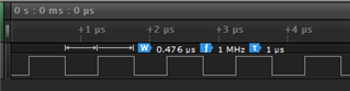
    Then observe output signal:

  • Thanks for your help. Next, I would like to do is generate a bitstream updating in negative clock edges. However, with GPIOTE tasks I can only set/clear/toggle an output. Is there any way to index an array and assign the indexed value to the output with GPIOTE tasks?

    Thanks in advance!

  • No, you could do something like this by bitbangig, but then with much lower frequency. If you want to send any data at such high rates with the nRF5 the only real option is to use SPI. With that, the peripheral read and write data direct from/to RAM using DMA, so the transaction itself requires no CPU.

Related