This post is older than 2 years and might not be relevant anymore
More Info: Consider searching for newer posts

Implementing an external button for nRF52 DK

I want to add an external button that mimics the properties of the buttons in the nRF52 DK.  I read that the switches are all active low, so I assume that this means they are internally connected to a pull up resistor connected to a 5V source. So to mimic their properties my external circuit would need to have a pull up resistor connected to a 5V source, and closing the switch would ground the circuit, correct?

On the device datasheet it lists the GPIO pins as 13-16 which are all connected to the buttons.  If I want to replace the nRF52 DK button with my external button, I need to ground the shield detect pin to first enable these pins for I/O use, correct? And is there a way to only disconnect one of the switches through the shield detect or cutting connections?  I only want to use one button for my external switch and still want to use the other LEDs/buttons on the board. 

Thanks for the help!

Parents
  • I assume that this means they are internally connected to a pull up resistor connected to a 3.3V source.

    Rather than assume, you could look at the schematics.

    If I want to replace the nRF52 DK button with my external button

    If the internal button is never going to be used, you can just connect your external button in parallel 

  • Assume was a poor word choice.  I was basing that statement off of this paragraph in the documentation:

    "The buttons are active low, meaning the input will be connected to ground when the button is activated. The buttons have no external pull-up resistor, so to use the buttons the P0.13P0.16 pins must be configured as an input with an internal pull-up resistor."

    I couldn't find anything about the voltage associated with the referenced internal pull-up resistor, and since the board has both 5V and 3.3V power options I wasn't sure which power source the pins were using.  I assumed 3.3V initially since that seems to be what the board typically runs off of, but I ran a quick test with the switch connected to 5V and it worked, so it seems that either power option would suffice.  If there is something in the documentation that I missed I apologize.

    I also tried the circuit with the shield detect grounded and ungrounded and both circuits worked.  I couldn't find anything in the documentation about what happens if I connected I/O to the GPIO pins while they are still connected to the DK buttons.  If someone could clear this up it would be helpful as well as the behavior seems to have both buttons working in parallel when the shield detect isn't grounded and I just want to confirm if this is what's going on.

  • Hi,

    jake11212 said:

    "The buttons are active low, meaning the input will be connected to ground when the button is activated. The buttons have no external pull-up resistor, so to use the buttons the P0.13P0.16 pins must be configured as an input with an internal pull-up resistor."

     The pin that is connected to the button are pulled up internally to VDD which usually is 3V3 if USB is used. See the backside of the DK, it has an illustration that explains the connection.

    jake11212 said:
    I also tried the circuit with the shield detect grounded and ungrounded and both circuits worked.  I couldn't find anything in the documentation about what happens if I connected I/O to the GPIO pins while they are still connected to the DK buttons.  If someone could clear this up it would be helpful as well as the behavior seems to have both buttons working in parallel when the shield detect isn't grounded and I just want to confirm if this is what's going on.

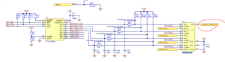
    Yes, you would have to ground SHIELD DETECTED to free the pins. The pins are routed through a NX3DV2567 switch, which means that you can't separate which button that is disconnected. See the schematic:

    best regards

    Jared 

Reply
  • Hi,

    jake11212 said:

    "The buttons are active low, meaning the input will be connected to ground when the button is activated. The buttons have no external pull-up resistor, so to use the buttons the P0.13P0.16 pins must be configured as an input with an internal pull-up resistor."

     The pin that is connected to the button are pulled up internally to VDD which usually is 3V3 if USB is used. See the backside of the DK, it has an illustration that explains the connection.

    jake11212 said:
    I also tried the circuit with the shield detect grounded and ungrounded and both circuits worked.  I couldn't find anything in the documentation about what happens if I connected I/O to the GPIO pins while they are still connected to the DK buttons.  If someone could clear this up it would be helpful as well as the behavior seems to have both buttons working in parallel when the shield detect isn't grounded and I just want to confirm if this is what's going on.

    Yes, you would have to ground SHIELD DETECTED to free the pins. The pins are routed through a NX3DV2567 switch, which means that you can't separate which button that is disconnected. See the schematic:

    best regards

    Jared 

Children
No Data
Related