

Hi,
I am trying to run the NCS Zephyr ADXL372 sensor sample application (using nRF5340 DK) but get the following error:
Could not get ADXL372 device
[00:00:00.000,518] [1B][1;31m<err> i2c_nrfx_twim: Error 195952641 occurred for message 0[1B][0m
This corresponds to the following NACK error:
NRFX_ERROR_DRV_TWI_ERR_ANACK = (NRFX_ERROR_DRIVERS_BASE_NUM + 1), ///< TWI error: Address not acknowledged.
I have stepped through debugging and see that it is unable to communicate with the ADXL372 using the NCS/Zephyr driver. Basically the ADXL372 driver fails its init/probe routine because it cannot read from the ADXL372. I cannot figure out why this is failing to read, I will attach my project files and zephyr.dts build files below. I have a feeling it is either an error in my overlay config or my wiring.
Project Files:
main.c :
/*
 * Copyright (c) 2018 Analog Devices Inc.
 *
 * SPDX-License-Identifier: Apache-2.0
 */

#include <zephyr.h>
#include <drivers/sensor.h>
#include <stdio.h>

#define pow2(x) ((x) * (x))

static double sqrt(double value)
{
	int i;
	double sqrt = value / 3;

	if (value <= 0) {
		return 0;
	}

	for (i = 0; i < 6; i++) {
		sqrt = (sqrt + value / sqrt) / 2;
	}

	return sqrt;
}

K_SEM_DEFINE(sem, 0, 1);

static void trigger_handler(const struct device *dev,
			    struct sensor_trigger *trigger)
{
	ARG_UNUSED(trigger);

	if (sensor_sample_fetch(dev)) {
		printf("sensor_sample_fetch failed\n");
		return;
	}

	k_sem_give(&sem);
}

void main(void)
{
	struct sensor_value accel[3];
	double mag;
	int i;
	char meter[200];

	const struct device *dev = device_get_binding(DT_LABEL(DT_INST(0, adi_adxl372)));

	if (dev == NULL) {
		printf("Could not get %s device\n", DT_LABEL(DT_INST(0, adi_adxl372)));
		return;
	}

	struct sensor_trigger trig = {
		.type = SENSOR_TRIG_DATA_READY,
		.chan = SENSOR_CHAN_ACCEL_XYZ,
	};

	if (IS_ENABLED(CONFIG_ADXL372_PEAK_DETECT_MODE)) {
		trig.type = SENSOR_TRIG_THRESHOLD;
	}

	if (IS_ENABLED(CONFIG_ADXL372_TRIGGER)) {
		if (sensor_trigger_set(dev, &trig, trigger_handler)) {
			printf("Could not set trigger\n");
			return;
		}
	}

	while (1) {
		if (IS_ENABLED(CONFIG_ADXL372_TRIGGER)) {
			if (IS_ENABLED(CONFIG_ADXL372_PEAK_DETECT_MODE)) {
				printf("Waiting for a threshold event\n");
			}
			k_sem_take(&sem, K_FOREVER);
		} else {
			if (sensor_sample_fetch(dev)) {
				printf("sensor_sample_fetch failed\n");
			}
		}

		sensor_channel_get(dev, SENSOR_CHAN_ACCEL_XYZ, accel);

		if (IS_ENABLED(CONFIG_ADXL372_PEAK_DETECT_MODE)) {
			mag = sqrt(pow2(sensor_ms2_to_g(&accel[0])) +
				pow2(sensor_ms2_to_g(&accel[1])) +
				pow2(sensor_ms2_to_g(&accel[2])));

			for (i = 0; i <= mag && i < (sizeof(meter) - 1); i++) {
				meter[i] = '#';
			}

			meter[i] = '\0';

			printf("%6.2f g: %s\n", mag, meter);
		} else {
			printf("AX=%10.2f AY=%10.2f AZ=%10.2f (m/s^2)\n",
				sensor_value_to_double(&accel[0]),
				sensor_value_to_double(&accel[1]),
				sensor_value_to_double(&accel[2]));
		}

		if (!IS_ENABLED(CONFIG_ADXL372_TRIGGER)) {
			k_sleep(K_MSEC(2000));
		}
	}
}
nrf5340dk_nrf5340_cpuappns.overlay :
/*
 * Copyright (c) 2019 Linaro Limited
 *
 * SPDX-License-Identifier: Apache-2.0
 */


&i2c1 {
	compatible = "nordic,nrf-twim";
	status = "okay";
	sda-pin = < 9 >;
	scl-pin = < 10 >;
    clock-frequency = <I2C_BITRATE_STANDARD>;

	adi_adxl372: adxl372@53 {
		compatible = "adi,adxl372";
		reg = <0x53>;
		label = "ADXL372";
		int1-gpios = <&gpio0 11 0>;
	};
};


/*&spi2 {
	compatible = "nordic,nrf-spim";
	status = "okay";
	mosi-pin = <10>;
	miso-pin = <7>;
	sck-pin = <9>;

	cs-gpios = <&gpio0 22 GPIO_ACTIVE_LOW>;
	adxl372@0 {
		compatible = "adi,adxl372";
		reg = <0>;
		spi-max-frequency = <8000000>;
		label = "ADXL372";
		int1-gpios = <&gpio0 11 GPIO_ACTIVE_HIGH>;
	};
};*/
prj.conf :
CONFIG_STDOUT_CONSOLE=y
CONFIG_LOG=y

CONFIG_I2C=y
#CONFIG_I2C_NRFX=y	#not sure if this is needed, not part of the example config
#CONFIG_SPI=y	#use this instead of CONFIG_I2C=y for SPI

CONFIG_SENSOR=y
CONFIG_ADXL372=y

CONFIG_ADXL372_I2C=y
#CONFIG_ADXL372_SPI=y	#use this instead of CONFIG_ADXL372_I2C=y for SPI

CONFIG_SENSOR_LOG_LEVEL_WRN=y

#CONFIG_CBPRINTF_FP_SUPPORT=y	#use this when using SPI
CMakeLists.txt :
#
#  Copyright (c) 2018 Analog Devices Inc.
#
#  SPDX-License-Identifier: Apache-2.0
#
cmake_minimum_required(VERSION 3.13.1)

set(TEST_DTC_OVERLAY_FILE
  ${CMAKE_CURRENT_SOURCE_DIR}/nrf5340dk_nrf5340_cpuappns.overlay
)

set(PRJ_CONF_FILE
  prj.conf
  ${CMAKE_CURRENT_LIST_DIR}/prj.conf
)

find_package(Zephyr REQUIRED HINTS $ENV{ZEPHYR_BASE})
project(adxl372)
zephyr_include_directories(include)

FILE(GLOB app_sources src/*.c)
target_sources(app PRIVATE ${app_sources})
build/zephyr/zephyr.dts :
/dts-v1/;

/ {
	#address-cells = < 0x1 >;
	#size-cells = < 0x1 >;
	model = "Nordic NRF5340 DK NRF5340 Application";
	compatible = "nordic,nrf5340-dk-nrf5340-cpuapp";
	chosen {
		zephyr,flash-controller = &flash_controller;
		zephyr,entropy = &cryptocell_sw;
		zephyr,console = &uart0;
		zephyr,shell-uart = &uart0;
		zephyr,uart-mcumgr = &uart0;
		zephyr,bt-mon-uart = &uart0;
		zephyr,bt-c2h-uart = &uart0;
		zephyr,ipc_shm = &sram0_shared;
		zephyr,sram = &sram0_ns;
		zephyr,flash = &flash0;
		zephyr,code-partition = &slot0_ns_partition;
	};
	aliases {
		led0 = &led0;
		led1 = &led1;
		led2 = &led2;
		led3 = &led3;
		sw0 = &button0;
		sw1 = &button1;
		sw2 = &button2;
		sw3 = &button3;
	};
	soc {
		#address-cells = < 0x1 >;
		#size-cells = < 0x1 >;
		compatible = "nordic,nRF5340-CPUAPP-QKAA", "nordic,nRF5340-CPUAPP", "nordic,nRF53", "simple-bus";
		interrupt-parent = < &nvic >;
		ranges;
		nvic: interrupt-controller@e000e100 {
			compatible = "arm,v8m-nvic";
			reg = < 0xe000e100 0xc00 >;
			interrupt-controller;
			#interrupt-cells = < 0x2 >;
			arm,num-irq-priority-bits = < 0x3 >;
			phandle = < 0x1 >;
		};
		systick: timer@e000e010 {
			compatible = "arm,armv8m-systick";
			reg = < 0xe000e010 0x10 >;
			status = "disabled";
		};
		sram0: memory@20000000 {
			compatible = "mmio-sram";
			reg = < 0x20000000 0x80000 >;
		};
		sram1: memory@21000000 {
			compatible = "mmio-sram";
			reg = < 0x21000000 0x10000 >;
		};
		peripheral@40000000 {
			#address-cells = < 0x1 >;
			#size-cells = < 0x1 >;
			ranges = < 0x0 0x40000000 0x10000000 >;
			flash_controller: flash-controller@39000 {
				compatible = "nordic,nrf53-flash-controller";
				reg = < 0x39000 0x1000 >;
				#address-cells = < 0x1 >;
				#size-cells = < 0x1 >;
				label = "NRF_FLASH_DRV_NAME";
				flash0: flash@0 {
					compatible = "soc-nv-flash";
					label = "NRF_FLASH";
					erase-block-size = < 0x1000 >;
					write-block-size = < 0x4 >;
					reg = < 0x0 0x100000 >;
					partitions {
						compatible = "fixed-partitions";
						#address-cells = < 0x1 >;
						#size-cells = < 0x1 >;
						boot_partition: partition@0 {
							label = "mcuboot";
							reg = < 0x0 0x10000 >;
						};
						slot0_partition: partition@10000 {
							label = "image-0";
							reg = < 0x10000 0x40000 >;
						};
						slot0_ns_partition: partition@50000 {
							label = "image-0-nonsecure";
							reg = < 0x50000 0x30000 >;
						};
						slot1_partition: partition@80000 {
							label = "image-1";
							reg = < 0x80000 0x40000 >;
						};
						slot1_ns_partition: partition@c0000 {
							label = "image-1-nonsecure";
							reg = < 0xc0000 0x30000 >;
						};
						scratch_partition: partition@f0000 {
							label = "image-scratch";
							reg = < 0xf0000 0xa000 >;
						};
						storage_partition: partition@fa000 {
							label = "storage";
							reg = < 0xfa000 0x6000 >;
						};
					};
				};
			};
			adc: adc@e000 {
				compatible = "nordic,nrf-saadc";
				reg = < 0xe000 0x1000 >;
				interrupts = < 0xe 0x1 >;
				status = "okay";
				label = "ADC_0";
				#io-channel-cells = < 0x1 >;
			};
			dppic: dppic@17000 {
				compatible = "nordic,nrf-dppic";
				reg = < 0x17000 0x1000 >;
				status = "okay";
				label = "DPPIC";
			};
			egu0: egu@1b000 {
				compatible = "nordic,nrf-egu";
				reg = < 0x1b000 0x1000 >;
				interrupts = < 0x1b 0x1 >;
				status = "okay";
			};
			egu1: egu@1c000 {
				compatible = "nordic,nrf-egu";
				reg = < 0x1c000 0x1000 >;
				interrupts = < 0x1c 0x1 >;
				status = "okay";
			};
			egu2: egu@1d000 {
				compatible = "nordic,nrf-egu";
				reg = < 0x1d000 0x1000 >;
				interrupts = < 0x1d 0x1 >;
				status = "okay";
			};
			egu3: egu@1e000 {
				compatible = "nordic,nrf-egu";
				reg = < 0x1e000 0x1000 >;
				interrupts = < 0x1e 0x1 >;
				status = "okay";
			};
			egu4: egu@1f000 {
				compatible = "nordic,nrf-egu";
				reg = < 0x1f000 0x1000 >;
				interrupts = < 0x1f 0x1 >;
				status = "okay";
			};
			egu5: egu@20000 {
				compatible = "nordic,nrf-egu";
				reg = < 0x20000 0x1000 >;
				interrupts = < 0x20 0x1 >;
				status = "okay";
			};
			i2s0: i2s@28000 {
				compatible = "nordic,nrf-i2s";
				#address-cells = < 0x1 >;
				#size-cells = < 0x0 >;
				reg = < 0x28000 0x1000 >;
				interrupts = < 0x28 0x1 >;
				status = "disabled";
				label = "I2S_0";
			};
			ipc: ipc@2a000 {
				compatible = "nordic,nrf-ipc";
				reg = < 0x2a000 0x1000 >;
				interrupts = < 0x2a 0x1 >;
				status = "okay";
				label = "IPC";
			};
			kmu: kmu@39000 {
				compatible = "nordic,nrf-kmu";
				reg = < 0x39000 0x1000 >;
				interrupts = < 0x39 0x1 >;
				status = "okay";
			};
			pdm0: pdm@26000 {
				compatible = "nordic,nrf-pdm";
				reg = < 0x26000 0x1000 >;
				interrupts = < 0x26 0x1 >;
				status = "disabled";
				label = "PDM_0";
			};
			regulators: regulator@4000 {
				compatible = "nordic,nrf-regulators";
				reg = < 0x4000 0x1000 >;
				status = "okay";
			};
			vmc: vmc@81000 {
				compatible = "nordic,nrf-vmc";
				reg = < 0x81000 0x1000 >;
				status = "okay";
			};
			uart0: uart@8000 {
				compatible = "nordic,nrf-uarte";
				reg = < 0x8000 0x1000 >;
				interrupts = < 0x8 0x1 >;
				status = "okay";
				label = "UART_0";
				current-speed = < 0x1c200 >;
				tx-pin = < 0x14 >;
				rx-pin = < 0x16 >;
				rts-pin = < 0x13 >;
				cts-pin = < 0x15 >;
			};
			uart1: uart@9000 {
				compatible = "nordic,nrf-uarte";
				reg = < 0x9000 0x1000 >;
				interrupts = < 0x9 0x1 >;
				status = "disabled";
				label = "UART_1";
			};
			uart2: uart@b000 {
				compatible = "nordic,nrf-uarte";
				reg = < 0xb000 0x1000 >;
				interrupts = < 0xb 0x1 >;
				status = "disabled";
				label = "UART_2";
			};
			uart3: uart@c000 {
				compatible = "nordic,nrf-uarte";
				reg = < 0xc000 0x1000 >;
				interrupts = < 0xc 0x1 >;
				status = "disabled";
				label = "UART_3";
			};
			i2c0: i2c@8000 {
				#address-cells = < 0x1 >;
				#size-cells = < 0x0 >;
				reg = < 0x8000 0x1000 >;
				clock-frequency = < 0x186a0 >;
				interrupts = < 0x8 0x1 >;
				status = "disabled";
				label = "I2C_0";
			};
			i2c1: i2c@9000 {
				#address-cells = < 0x1 >;
				#size-cells = < 0x0 >;
				reg = < 0x9000 0x1000 >;
				clock-frequency = < 0x186a0 >;
				interrupts = < 0x9 0x1 >;
				status = "okay";
				label = "I2C_1";
				compatible = "nordic,nrf-twim";
				sda-pin = < 0x9 >;
				scl-pin = < 0xa >;
				adi_adxl372: adxl372@53 {
					compatible = "adi,adxl372";
					reg = < 0x53 >;
					label = "ADXL372";
					int1-gpios = < &gpio0 0xb 0x0 >;
				};
			};
			i2c2: i2c@b000 {
				#address-cells = < 0x1 >;
				#size-cells = < 0x0 >;
				reg = < 0xb000 0x1000 >;
				clock-frequency = < 0x186a0 >;
				interrupts = < 0xb 0x1 >;
				status = "disabled";
				label = "I2C_2";
			};
			i2c3: i2c@c000 {
				#address-cells = < 0x1 >;
				#size-cells = < 0x0 >;
				reg = < 0xc000 0x1000 >;
				clock-frequency = < 0x186a0 >;
				interrupts = < 0xc 0x1 >;
				status = "disabled";
				label = "I2C_3";
			};
			spi0: spi@8000 {
				#address-cells = < 0x1 >;
				#size-cells = < 0x0 >;
				reg = < 0x8000 0x1000 >;
				interrupts = < 0x8 0x1 >;
				status = "disabled";
				label = "SPI_0";
			};
			spi1: spi@9000 {
				#address-cells = < 0x1 >;
				#size-cells = < 0x0 >;
				reg = < 0x9000 0x1000 >;
				interrupts = < 0x9 0x1 >;
				status = "disabled";
				label = "SPI_1";
			};
			spi2: spi@b000 {
				#address-cells = < 0x1 >;
				#size-cells = < 0x0 >;
				reg = < 0xb000 0x1000 >;
				interrupts = < 0xb 0x1 >;
				status = "disabled";
				label = "SPI_2";
			};
			spi3: spi@c000 {
				#address-cells = < 0x1 >;
				#size-cells = < 0x0 >;
				reg = < 0xc000 0x1000 >;
				interrupts = < 0xc 0x1 >;
				status = "disabled";
				label = "SPI_3";
			};
			spi4: spi@a000 {
				compatible = "nordic,nrf-spim";
				#address-cells = < 0x1 >;
				#size-cells = < 0x0 >;
				reg = < 0xa000 0x1000 >;
				interrupts = < 0xa 0x1 >;
				status = "disabled";
				label = "SPI_4";
			};
			pwm0: pwm@21000 {
				compatible = "nordic,nrf-pwm";
				reg = < 0x21000 0x1000 >;
				interrupts = < 0x21 0x1 >;
				status = "okay";
				label = "PWM_0";
				#pwm-cells = < 0x1 >;
				ch0-pin = < 0x1c >;
			};
			pwm1: pwm@22000 {
				compatible = "nordic,nrf-pwm";
				reg = < 0x22000 0x1000 >;
				interrupts = < 0x22 0x1 >;
				status = "disabled";
				label = "PWM_1";
				#pwm-cells = < 0x1 >;
			};
			pwm2: pwm@23000 {
				compatible = "nordic,nrf-pwm";
				reg = < 0x23000 0x1000 >;
				interrupts = < 0x23 0x1 >;
				status = "disabled";
				label = "PWM_2";
				#pwm-cells = < 0x1 >;
			};
			pwm3: pwm@24000 {
				compatible = "nordic,nrf-pwm";
				reg = < 0x24000 0x1000 >;
				interrupts = < 0x24 0x1 >;
				status = "disabled";
				label = "PWM_3";
				#pwm-cells = < 0x1 >;
			};
			gpio0: gpio@842500 {
				compatible = "nordic,nrf-gpio";
				gpio-controller;
				reg = < 0x842500 0x300 >;
				#gpio-cells = < 0x2 >;
				label = "GPIO_0";
				status = "okay";
				port = < 0x0 >;
				phandle = < 0x2 >;
			};
			gpio1: gpio@842800 {
				compatible = "nordic,nrf-gpio";
				gpio-controller;
				reg = < 0x842800 0x300 >;
				#gpio-cells = < 0x2 >;
				ngpios = < 0x10 >;
				label = "GPIO_1";
				status = "okay";
				port = < 0x1 >;
			};
			qspi: qspi@2b000 {
				compatible = "nordic,nrf-qspi";
				#address-cells = < 0x1 >;
				#size-cells = < 0x0 >;
				reg = < 0x2b000 0x1000 >;
				interrupts = < 0x2b 0x1 >;
				status = "okay";
				label = "QSPI";
				sck-pin = < 0x11 >;
				io-pins = < 0xd >, < 0xe >, < 0xf >, < 0x10 >;
				csn-pins = < 0x12 >;
				mx25r64: mx25r6435f@0 {
					compatible = "nordic,qspi-nor";
					reg = < 0x0 >;
					writeoc = "pp4io";
					readoc = "read4io";
					sck-frequency = < 0x7a1200 >;
					label = "MX25R64";
					jedec-id = [ C2 28 17 ];
					sfdp-bfp = [ E5 20 F1 FF FF FF FF 03 44 EB 08 6B 08 3B 04 BB EE FF FF FF FF FF 00 FF FF FF 00 FF 0C 20 0F 52 10 D8 00 FF 23 72 F5 00 82 ED 04 CC 44 83 68 44 30 B0 30 B0 F7 C4 D5 5C 00 BE 29 FF F0 D0 FF FF ];
					size = < 0x4000000 >;
					has-dpd;
					t-enter-dpd = < 0x2710 >;
					t-exit-dpd = < 0x88b8 >;
				};
			};
			rtc0: rtc@14000 {
				compatible = "nordic,nrf-rtc";
				reg = < 0x14000 0x1000 >;
				cc-num = < 0x4 >;
				interrupts = < 0x14 0x1 >;
				status = "okay";
				clock-frequency = < 0x8000 >;
				prescaler = < 0x1 >;
				label = "RTC_0";
			};
			rtc1: rtc@15000 {
				compatible = "nordic,nrf-rtc";
				reg = < 0x15000 0x1000 >;
				cc-num = < 0x4 >;
				interrupts = < 0x15 0x1 >;
				status = "okay";
				clock-frequency = < 0x8000 >;
				prescaler = < 0x1 >;
				label = "RTC_1";
			};
			clock: clock@5000 {
				compatible = "nordic,nrf-clock";
				reg = < 0x5000 0x1000 >;
				interrupts = < 0x5 0x1 >;
				status = "okay";
				label = "CLOCK";
			};
			power: power@5000 {
				compatible = "nordic,nrf-power";
				reg = < 0x5000 0x1000 >;
				interrupts = < 0x5 0x1 >;
				status = "okay";
			};
			wdt: wdt0: watchdog@18000 {
				compatible = "nordic,nrf-watchdog";
				reg = < 0x18000 0x1000 >;
				interrupts = < 0x18 0x1 >;
				status = "okay";
				label = "WDT";
			};
			wdt1: watchdog@19000 {
				compatible = "nordic,nrf-watchdog";
				reg = < 0x19000 0x1000 >;
				interrupts = < 0x19 0x1 >;
				status = "disabled";
				label = "WDT_1";
			};
			timer0: timer@f000 {
				compatible = "nordic,nrf-timer";
				status = "okay";
				reg = < 0xf000 0x1000 >;
				cc-num = < 0x6 >;
				interrupts = < 0xf 0x1 >;
				prescaler = < 0x0 >;
				label = "TIMER_0";
			};
			timer1: timer@10000 {
				compatible = "nordic,nrf-timer";
				status = "okay";
				reg = < 0x10000 0x1000 >;
				cc-num = < 0x6 >;
				interrupts = < 0x10 0x1 >;
				prescaler = < 0x0 >;
				label = "TIMER_1";
			};
			timer2: timer@11000 {
				compatible = "nordic,nrf-timer";
				status = "okay";
				reg = < 0x11000 0x1000 >;
				cc-num = < 0x6 >;
				interrupts = < 0x11 0x1 >;
				prescaler = < 0x0 >;
				label = "TIMER_2";
			};
			usbd: usbd@36000 {
				compatible = "nordic,nrf-usbd";
				reg = < 0x36000 0x1000 >;
				interrupts = < 0x36 0x1 >;
				num-bidir-endpoints = < 0x1 >;
				num-in-endpoints = < 0x7 >;
				num-out-endpoints = < 0x7 >;
				num-isoin-endpoints = < 0x1 >;
				num-isoout-endpoints = < 0x1 >;
				status = "okay";
				label = "USBD";
			};
		};
		gpiote: gpiote@4002f000 {
			compatible = "nordic,nrf-gpiote";
			reg = < 0x4002f000 0x1000 >;
			interrupts = < 0x2f 0x5 >;
			status = "okay";
			label = "GPIOTE_1";
		};
		cryptocell_sw: cryptocell-sw {
			compatible = "nordic,nrf-cc312-sw";
			#address-cells = < 0x0 >;
			label = "CRYPTOCELL_SW";
		};
	};
	cpus {
		#address-cells = < 0x1 >;
		#size-cells = < 0x0 >;
		cpu@0 {
			device_type = "cpu";
			compatible = "arm,cortex-m33f";
			reg = < 0x0 >;
			#address-cells = < 0x1 >;
			#size-cells = < 0x1 >;
			mpu: mpu@e000ed90 {
				compatible = "arm,armv8m-mpu";
				reg = < 0xe000ed90 0x40 >;
				arm,num-mpu-regions = < 0x8 >;
			};
		};
	};
	leds {
		compatible = "gpio-leds";
		led0: led_0 {
			gpios = < &gpio0 0x1c 0x1 >;
			label = "Green LED 0";
		};
		led1: led_1 {
			gpios = < &gpio0 0x1d 0x1 >;
			label = "Green LED 1";
		};
		led2: led_2 {
			gpios = < &gpio0 0x1e 0x1 >;
			label = "Green LED 2";
		};
		led3: led_3 {
			gpios = < &gpio0 0x1f 0x1 >;
			label = "Green LED 3";
		};
	};
	buttons {
		compatible = "gpio-keys";
		button0: button_0 {
			gpios = < &gpio0 0x17 0x11 >;
			label = "Push button 1";
		};
		button1: button_1 {
			gpios = < &gpio0 0x18 0x11 >;
			label = "Push button 2";
		};
		button2: button_2 {
			gpios = < &gpio0 0x8 0x11 >;
			label = "Push button 3";
		};
		button3: button_3 {
			gpios = < &gpio0 0x9 0x11 >;
			label = "Push button 4";
		};
	};
	reserved-memory {
		#address-cells = < 0x1 >;
		#size-cells = < 0x1 >;
		ranges;
		sram0_image: image@20000000 {
			reg = < 0x20000000 0x70000 >;
		};
		sram0_s: image_s@20000000 {
			reg = < 0x20000000 0x40000 >;
		};
		sram0_ns: image_ns@20040000 {
			reg = < 0x20040000 0x30000 >;
		};
		sram0_shared: memory@20070000 {
			reg = < 0x20070000 0x10000 >;
		};
	};
};
Hardware/test-bench setup:
So I am using the ADXL372Z (EVALUATION BOARD / MODEL) to be specific. From what I can tell there is no difference between this and the ADXL372 besides packaging.
This is the schematic/pinout provided for the ADXL372Z: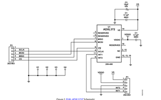
These are my notes on I2C wiring and how the ADXL372 is wired to my 5340dk (referencing above schematic):
ADXL Pin | Logic | 5340DK Pin
P2 MOSI	 = 	SDA  = 	P0.09 (4.7k Ohm pull-up to VDD)
P2 CS 	 = 	SCL	 = 	P0.10 (4.7k Ohm pull-up to VDD)
P1 INT1  = 	INT	 = 	P0.11
P2 SCLK  = 	GND	 = 	GND
P2 MISO  = 	GND	 = 	VDD	  (pulled low I2C address = 0x1D, pulled high I2C address = 0x53)
P2 GND   = 	GND  = 	GND
P1 GND 	 = 	GND  = 	GND
P1 VS 	 = 	VDD  = 	VDD
P1 VIO   = 	VDD  = 	VDD
Any help would be appreciated. I will add that I wasn't able to get it working using SPI the other day either but I don't really care about SPI so not too important.
