This post is older than 2 years and might not be relevant anymore
More Info: Consider searching for newer posts

I want to make an optimized spi clock.

The SDK version is using version 17 and I am using NRF52832.

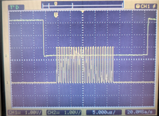
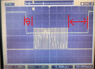
I checked the following scope waveform for the next SPI communication.
    

Question

  1. I want to remove the following area (delay).
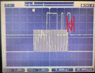
                

  2. Is it possible to change the voltage of that IO to 1.8 volts using the source code?
  • Looks like a Rigol scope? Note that they can save a screenshot to a USB stick - this will give a far clearer picture than a photo!

    It's not the clock that needs "optimising" - it's the CS line.

    So how are you currently managing the CS line?

  • I used the basic example code used in the SDK.

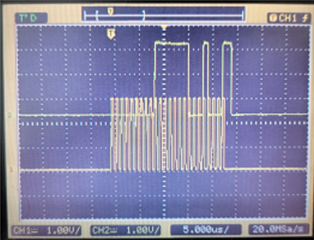
    I also want to get rid of the data that comes out after the clock (about 2 clocks).

    If there should be, why should it exist?

    /**
     * Copyright (c) 2015 - 2020, Nordic Semiconductor ASA
     *
     * All rights reserved.
     *
     * Redistribution and use in source and binary forms, with or without modification,
     * are permitted provided that the following conditions are met:
     *
     * 1. Redistributions of source code must retain the above copyright notice, this
     *    list of conditions and the following disclaimer.
     *
     * 2. Redistributions in binary form, except as embedded into a Nordic
     *    Semiconductor ASA integrated circuit in a product or a software update for
     *    such product, must reproduce the above copyright notice, this list of
     *    conditions and the following disclaimer in the documentation and/or other
     *    materials provided with the distribution.
     *
     * 3. Neither the name of Nordic Semiconductor ASA nor the names of its
     *    contributors may be used to endorse or promote products derived from this
     *    software without specific prior written permission.
     *
     * 4. This software, with or without modification, must only be used with a
     *    Nordic Semiconductor ASA integrated circuit.
     *
     * 5. Any software provided in binary form under this license must not be reverse
     *    engineered, decompiled, modified and/or disassembled.
     *
     * THIS SOFTWARE IS PROVIDED BY NORDIC SEMICONDUCTOR ASA "AS IS" AND ANY EXPRESS
     * OR IMPLIED WARRANTIES, INCLUDING, BUT NOT LIMITED TO, THE IMPLIED WARRANTIES
     * OF MERCHANTABILITY, NONINFRINGEMENT, AND FITNESS FOR A PARTICULAR PURPOSE ARE
     * DISCLAIMED. IN NO EVENT SHALL NORDIC SEMICONDUCTOR ASA OR CONTRIBUTORS BE
     * LIABLE FOR ANY DIRECT, INDIRECT, INCIDENTAL, SPECIAL, EXEMPLARY, OR
     * CONSEQUENTIAL DAMAGES (INCLUDING, BUT NOT LIMITED TO, PROCUREMENT OF SUBSTITUTE
     * GOODS OR SERVICES; LOSS OF USE, DATA, OR PROFITS; OR BUSINESS INTERRUPTION)
     * HOWEVER CAUSED AND ON ANY THEORY OF LIABILITY, WHETHER IN CONTRACT, STRICT
     * LIABILITY, OR TORT (INCLUDING NEGLIGENCE OR OTHERWISE) ARISING IN ANY WAY OUT
     * OF THE USE OF THIS SOFTWARE, EVEN IF ADVISED OF THE POSSIBILITY OF SUCH DAMAGE.
     *
     */
    #include "nrf_drv_spi.h"
    #include "app_util_platform.h"
    #include "nrf_gpio.h"
    #include "nrf_delay.h"
    #include "boards.h"
    #include "app_error.h"
    #include <string.h>
    #include "nrf_log.h"
    #include "nrf_log_ctrl.h"
    #include "nrf_log_default_backends.h"
    
    #define SPI_INSTANCE  0 /**< SPI instance index. */
    static const nrf_drv_spi_t spi = NRF_DRV_SPI_INSTANCE(SPI_INSTANCE);  /**< SPI instance. */
    static volatile bool spi_xfer_done;  /**< Flag used to indicate that SPI instance completed the transfer. */
    
    #define TEST_STRING "No"
    static uint8_t       m_tx_buf[] = TEST_STRING;           /**< TX buffer. */
    static uint8_t       m_rx_buf[sizeof(TEST_STRING) + 1];    /**< RX buffer. */
    static const uint8_t m_length = sizeof(m_tx_buf);        /**< Transfer length. */
    
    static uint8_t       send_buf[3] = {0,0,0}; 
    static uint8_t       recived_buf[4];
    static const uint8_t send_length     = sizeof(send_buf); 
    /**
     * @brief SPI user event handler.
     * @param event
     */
    void spi_event_handler(nrf_drv_spi_evt_t const * p_event,
                           void *                    p_context)
    {
        spi_xfer_done = true;
        NRF_LOG_INFO("Transfer completed.");
        if (recived_buf[0] != 0)
        {
            NRF_LOG_INFO(" Received:");
            NRF_LOG_HEXDUMP_INFO(recived_buf, strlen((const char *)recived_buf));
        }
    }
    
    void spi_send(char addr, char Data_h, char Data_l){
    // Reset rx buffer and transfer done flag
            memset(recived_buf, 0, send_length);
            spi_xfer_done = false;
      send_buf[0]     = addr;
      send_buf[1]     = Data_l;
      send_buf[2]     = Data_h;
    
     while (!spi_xfer_done)
            {
                __WFE();
            }
    
            NRF_LOG_FLUSH();
    
      nrf_drv_spi_transfer(&spi, send_buf, send_length, recived_buf, send_length);
    }
    
    int main(void)
    {
        bsp_board_init(BSP_INIT_LEDS);
    
        APP_ERROR_CHECK(NRF_LOG_INIT(NULL));
        NRF_LOG_DEFAULT_BACKENDS_INIT();
    
        nrf_drv_spi_config_t spi_config = NRF_DRV_SPI_DEFAULT_CONFIG;
        spi_config.ss_pin   = SPI_SS_PIN;
        spi_config.miso_pin = SPI_MISO_PIN;
        spi_config.mosi_pin = SPI_MOSI_PIN;
        spi_config.sck_pin  = SPI_SCK_PIN;
        APP_ERROR_CHECK(nrf_drv_spi_init(&spi, &spi_config, spi_event_handler, NULL));
    
        NRF_LOG_INFO("SPI example started.");
    
        while (1)
        {
            
            
            spi_send(0x11,0x01,0x7f);
            //APP_ERROR_CHECK(nrf_drv_spi_transfer(&spi, m_tx_buf, m_length, m_rx_buf, m_length));


            bsp_board_led_invert(BSP_BOARD_LED_0);
            nrf_delay_ms(200);
        }
    }
    

  • data that comes out after the clock (about 2 clocks).

    There is no data after the clock; that's just the MOSI returning to its idle 'low' state.

  • For the nRF52832 the SPI hardware peripheral handle the MISO, MOSI and CLK pin. So before and after every SPI transaction the application or driver will need to handle the CS pin, for instance from the interrupt handler after the SPI transmission have finished, so there will be some delays.

    If you use the nRF52840 you can find that the 4th SPI instance (SPIM3) have hardware support also for CS pin:
    https://infocenter.nordicsemi.com/topic/ps_nrf52840/spim.html#topic 

Related