Hi Nordic,
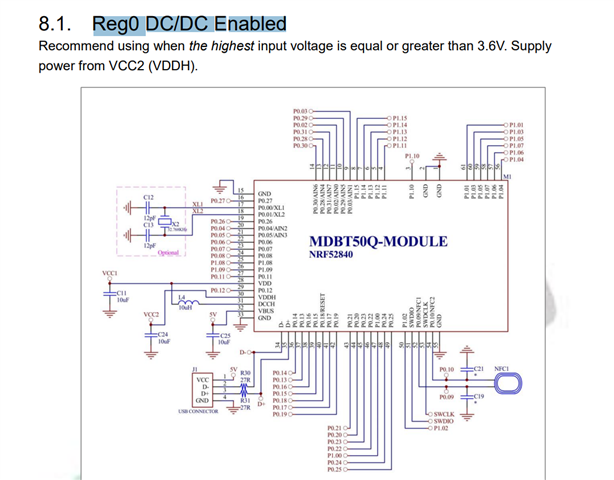
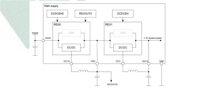
I am using the Raytac module with the nrf52840 inside, I have set my hardware as mode of Reg0 DC/DC enabled. Which disconnected the VDD and VDDH. Also I have givrn the 3.9-4.2V to the pin VDDH. In my code I setup output voltage to be 1.8V, but still output to be 3.3V, any idea for why not 1.8V for GPIO output?
static void gpio_output_voltage_setup_1_8(void)
{
    // Configure UICR_REGOUT0 register only if it is set to default value.
    if ((NRF_UICR->REGOUT0 & UICR_REGOUT0_VOUT_Msk) ==
        (UICR_REGOUT0_VOUT_DEFAULT << UICR_REGOUT0_VOUT_Pos))
    {
        NRF_NVMC->CONFIG = NVMC_CONFIG_WEN_Wen;
        while (NRF_NVMC->READY == NVMC_READY_READY_Busy){}

        NRF_UICR->REGOUT0 = (NRF_UICR->REGOUT0 & ~((uint32_t)UICR_REGOUT0_VOUT_Msk)) |
                            (UICR_REGOUT0_VOUT_1V8 << UICR_REGOUT0_VOUT_Pos);

        NRF_NVMC->CONFIG = NVMC_CONFIG_WEN_Ren;
        while (NRF_NVMC->READY == NVMC_READY_READY_Busy){}

        // System reset is needed to update UICR registers.
        NVIC_SystemReset();


    }
	else
	{
	 #ifdef DEBUG_UART_INFO_RTT_PRIVATE
          NRF_LOG_INFO("not setup_1_8\n");
	 #endif
	}
}

int main(void)
 {
   gpio_output_voltage_setup_1_8();