This post is older than 2 years and might not be relevant anymore
More Info: Consider searching for newer posts

Making 4 regular PWM signal.

Hello, guys. I'm using the PCA10040 and the SDK 16.0's BLE UART peripheral example. I am trying to make PWM signal below.

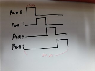
When PWM0 stops, PWM2 works, and when PWM2 stops, then PWM3, and in the same way, PWM4 works. And this signal is constantly repeated.

I tried to implement it only with the PWM SDK example, but I thought I needed other things to make it works, so I asked a question. please give me an advise.


Thank you for reding my issue.

Parents
  • Thank you for answer.
    Is nRF52832 impossible to do that?

    Here my code is

    app_pwm_config_t PWM_1_cfg = APP_PWM_DEFAULT_CONFIG_2CH(800L, 22, 23); // 0.8ms
    app_pwm_config_t PWM_2_cfg = APP_PWM_DEFAULT_CONFIG_2CH(800L, 24, 25); // 0.8ms

    g_s_bReadyFlag = false;
    while (app_pwm_channel_duty_set(&PWM_1, 0, 25) == NRF_ERROR_BUSY);
    while (!g_s_bReadyFlag);

    nrf_delay_us(200);
    g_s_bReadyFlag = false;
    while (app_pwm_channel_duty_set(&PWM_1, 1, 25) == NRF_ERROR_BUSY);
    while (!g_s_bReadyFlag);
    nrf_delay_us(200);

    g_s_bReadyFlag_2 = false;
    while (app_pwm_channel_duty_set(&PWM_2, 0, 25) == NRF_ERROR_BUSY);
    while (!g_s_bReadyFlag_2);
    nrf_delay_us(200);

    g_s_bReadyFlag_2 = false;
    while (app_pwm_channel_duty_set(&PWM_2, 1, 25) == NRF_ERROR_BUSY);
    while (!g_s_bReadyFlag_2);
    nrf_delay_us(200);
    If irun this code and check the scope, i can see that the 200 microsecond delay is not applied and almost the same output.
    The results were similar even when outputting separately one by one without controlling the two channels as a bundle.


Reply
  • Thank you for answer.
    Is nRF52832 impossible to do that?

    Here my code is

    app_pwm_config_t PWM_1_cfg = APP_PWM_DEFAULT_CONFIG_2CH(800L, 22, 23); // 0.8ms
    app_pwm_config_t PWM_2_cfg = APP_PWM_DEFAULT_CONFIG_2CH(800L, 24, 25); // 0.8ms

    g_s_bReadyFlag = false;
    while (app_pwm_channel_duty_set(&PWM_1, 0, 25) == NRF_ERROR_BUSY);
    while (!g_s_bReadyFlag);

    nrf_delay_us(200);
    g_s_bReadyFlag = false;
    while (app_pwm_channel_duty_set(&PWM_1, 1, 25) == NRF_ERROR_BUSY);
    while (!g_s_bReadyFlag);
    nrf_delay_us(200);

    g_s_bReadyFlag_2 = false;
    while (app_pwm_channel_duty_set(&PWM_2, 0, 25) == NRF_ERROR_BUSY);
    while (!g_s_bReadyFlag_2);
    nrf_delay_us(200);

    g_s_bReadyFlag_2 = false;
    while (app_pwm_channel_duty_set(&PWM_2, 1, 25) == NRF_ERROR_BUSY);
    while (!g_s_bReadyFlag_2);
    nrf_delay_us(200);
    If irun this code and check the scope, i can see that the 200 microsecond delay is not applied and almost the same output.
    The results were similar even when outputting separately one by one without controlling the two channels as a bundle.


Children
No Data
Related