This post is older than 2 years and might not be relevant anymore
More Info: Consider searching for newer posts

Making 4 regular PWM signal.

Hello, guys. I'm using the PCA10040 and the SDK 16.0's BLE UART peripheral example. I am trying to make PWM signal below.
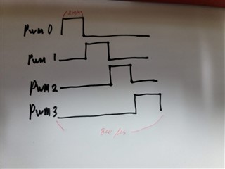
When PWM0 stops, PWM2 works, and when PWM2 stops, then PWM3, and in the same way, PWM4 works. And this signal is constantly repeated.

I tried to implement it only with the PWM SDK example, but I thought I needed other things to make it works, so I asked a question. please give me an advise.


Thank you for reding my issue.

Parents
  • Hi,

    I believe you can do this with four channels of a single PWM instance. Configure PWM with DECODER.LOAD=Single and create a four-step sequence, each step has zero compare value and POLARITY set for an active output:

    uint16_t pwmseq[16] = { 0x8000,0,0,0,  0,0x8000,0,0,  0,0,0x8000,0,  0,0,0,0x8000 };

    (I'm working with PWM peripheral directly rather than via app_pwm library, so I can't show a code sample with app_pwm)

Reply
  • Hi,

    I believe you can do this with four channels of a single PWM instance. Configure PWM with DECODER.LOAD=Single and create a four-step sequence, each step has zero compare value and POLARITY set for an active output:

    uint16_t pwmseq[16] = { 0x8000,0,0,0,  0,0x8000,0,0,  0,0,0x8000,0,  0,0,0,0x8000 };

    (I'm working with PWM peripheral directly rather than via app_pwm library, so I can't show a code sample with app_pwm)

Children
  • Hello Dmitry.

    First, thant you for answer.

    Do you mean creating an instance that controls 4 channels at oner?

    I only know the way that APP_PWM_DEFAULT_CONFIG_2CH(800L, 22, 23); So, please let me know how to do that?

    And i also can't find  DECODER.LOAD=Single.

    Thank you 

  • Hi,

    app_pwm is based on a timer and GPIOTE+PPI, it is limited with two channels per instance. Take a look at PWM driver, it uses hardware PWM peripheral that can drive four channels at once. 

    Here is a draft example how to configure pwm for 4 channels:

    static const nrfx_pwm_t pwm = NRFX_PWM_INSTANCE(0);
    
    static const nrfx_pwm_config_t pwm_config = {
        .output_pins = { 13,14,15,16 },
        .irq_priority = 3,
        .base_clock = NRF_PWM_CLK_1MHz,
        .count_mode = NRF_PWM_MODE_UP,
        .top_value = 200,
        .load_mode = NRF_PWM_LOAD_INDIVIDUAL,
        .step_mode = NRF_PWM_STEP_AUTO,
    };
    
    static uint16_t pwm_data[16] = { 0x8000,0,0,0,  0,0x8000,0,0,  0,0,0x8000,0,  0,0,0,0x8000 };
    
    static const nrf_pwm_sequence_t pwm_seq = {
        .values.p_raw = pwm_data,
        .length = NRF_PWM_VALUES_LENGTH(pwm_data),
        .repeats = 0,
        .end_delay = 0,
    };
    
    nrfx_pwm_init(&pwm, &pwm_config, NULL);
    nrfx_pwm_simple_playback(&pwm, &pwm_seq, 1, NRFX_PWM_FLAG_LOOP);
    

  • Hello,

     As you said, I've studied how to directly controf the PWM. Then i found out app_pwm_library is composed of PPI and GPIOTE, so i made the code while waiting for your reply.

     The code works the way i want it to. But i have a feeling that my code is forcing something to work. After running out of my code and looking at your answer, your code looks very convenient to extend and control like nRF_SDK.

     I attach my code below. And thank you so much for your help.

    #define MAX_SAMPLE_LEVEL     800
    #define SIXTY_SAMPLE_LEVEL   600
    #define HALF_SAMPLE_LEVEL    400
    #define QUARTER_SAMPLE_LEVEL 200
    
    void TIMER1_IRQHandler(void)
    {  
        if ((NRF_TIMER1->EVENTS_COMPARE[3] != 0) && ((NRF_TIMER1->INTENSET & TIMER_INTENSET_COMPARE3_Msk) != 0)) //TIMER_INTENSET_COMPARE1_Msk
        {
            //counter++;
            NRF_TIMER1->EVENTS_COMPARE[3] = 0;
            NRF_TIMER1->CC[0]             = (NRF_TIMER1->CC[0] + MAX_SAMPLE_LEVEL);
            NRF_TIMER1->CC[1]             = (NRF_TIMER1->CC[0] + QUARTER_SAMPLE_LEVEL);
            NRF_TIMER1->CC[2]             = (NRF_TIMER1->CC[0] + HALF_SAMPLE_LEVEL);  
            NRF_TIMER1->CC[3]             = (NRF_TIMER1->CC[0] + SIXTY_SAMPLE_LEVEL);
        }
    }
    
    void timer_INT_init(void)
    {
        //NRF_CLOCK->EVENTS_HFCLKSTARTED = 0;
        //NRF_CLOCK->TASKS_HFCLKSTART    = 1;
     
        //while (NRF_CLOCK->EVENTS_HFCLKSTARTED == 0)
        //{
        //    // Do nothing.
        //}
    
        NRF_TIMER1->MODE                    = TIMER_MODE_MODE_Timer << TIMER_MODE_MODE_Pos;
        NRF_TIMER1->BITMODE                 = TIMER_BITMODE_BITMODE_16Bit << TIMER_BITMODE_BITMODE_Pos;
        NRF_TIMER1->PRESCALER               = 4;
    
        NRF_TIMER1->TASKS_CLEAR = 1;    
    
        NRF_TIMER1->CC[0]                   = MAX_SAMPLE_LEVEL;      //800
        NRF_TIMER1->CC[1]                   = QUARTER_SAMPLE_LEVEL;  //200
        NRF_TIMER1->CC[2]                   = HALF_SAMPLE_LEVEL;     //400   
        NRF_TIMER1->CC[3]                   = SIXTY_SAMPLE_LEVEL;    //600
    
    
        NRF_TIMER1->INTENSET = (TIMER_INTENSET_COMPARE3_Enabled << TIMER_INTENSET_COMPARE3_Pos);
    
        NRF_POWER->TASKS_CONSTLAT = 1;
        NVIC_EnableIRQ(TIMER1_IRQn);
        __enable_irq();
        NRF_TIMER1->TASKS_START = 1;
    
    }
    
    void ppi_init(void)
    {
          nrf_gpio_cfg_output(PWM_A1);
          nrf_gpio_cfg_output(PWM_A2);
          nrf_gpio_cfg_output(PWM_B1);
          nrf_gpio_cfg_output(PWM_B2);
    
          nrf_gpiote_task_config( 0, PWM_A1, NRF_GPIOTE_POLARITY_TOGGLE, NRF_GPIOTE_INITIAL_VALUE_LOW);      //NRF_GPIOTE_INITIAL_VALUE_LOW
          nrf_gpiote_task_config( 1, PWM_A2, NRF_GPIOTE_POLARITY_TOGGLE, NRF_GPIOTE_INITIAL_VALUE_LOW);      //NRF_GPIOTE_INITIAL_VALUE_LOW
          nrf_gpiote_task_config( 2, PWM_B_PADL, NRF_GPIOTE_POLARITY_TOGGLE, NRF_GPIOTE_INITIAL_VALUE_LOW);  //NRF_GPIOTE_INITIAL_VALUE_LOW
          nrf_gpiote_task_config( 3, PWM_B1, NRF_GPIOTE_POLARITY_TOGGLE, NRF_GPIOTE_INITIAL_VALUE_HIGH);     //NRF_GPIOTE_INITIAL_VALUE_LOW
    
    
          NRF_PPI->CH[0].EEP  = (uint32_t)&NRF_TIMER1->EVENTS_COMPARE[0];  //800us Cycle
          NRF_PPI->CH[0].TEP  = (uint32_t)&NRF_GPIOTE->TASKS_OUT[0];                                        // Que>  SET SIGNAL  PWM_A1(22)  
          NRF_PPI->FORK[0].TEP = (uint32_t)&NRF_GPIOTE->TASKS_OUT[3];                                       // Que>  OFF SIGNAL  PWM_B2(25)  
    
          NRF_PPI->CH[1].EEP  = (uint32_t)&NRF_TIMER1->EVENTS_COMPARE[1]; // 200us Cycle
          NRF_PPI->CH[1].TEP  = (uint32_t)&NRF_GPIOTE->TASKS_OUT[0];                                        // Que> OFF SIGNAL   PWM_A1(22)                                           
          NRF_PPI->FORK[1].TEP = (uint32_t)&NRF_GPIOTE->TASKS_OUT[1];                                       // Que> SET SIGNAL   PWM_A2(23)                                        
    
          NRF_PPI->CH[2].EEP  = (uint32_t)&NRF_TIMER1->EVENTS_COMPARE[2]; // 400us Cycle
          NRF_PPI->CH[2].TEP  = (uint32_t)&NRF_GPIOTE->TASKS_OUT[1];                                        // Que> OFF SIGNAL   PWM_A2(23) 
          NRF_PPI->FORK[2].TEP = (uint32_t)&NRF_GPIOTE->TASKS_OUT[2];                                       // Que> SET SIGNAL   PWM_B1(24)   
    
          NRF_PPI->CH[3].EEP  = (uint32_t)&NRF_TIMER1->EVENTS_COMPARE[3]; // 600us Cycle
          NRF_PPI->CH[3].TEP  = (uint32_t)&NRF_GPIOTE->TASKS_OUT[2];                                        // Que> OFF SIGNAL   PWM_B1(24) 
          NRF_PPI->FORK[3].TEP = (uint32_t)&NRF_GPIOTE->TASKS_OUT[3];                                       // Que> SET SIGNAL   PWM_B2(25)  
    
    
          NRF_PPI->CHEN       = (PPI_CHEN_CH0_Enabled << PPI_CHEN_CH0_Pos) |
                                (PPI_CHEN_CH1_Enabled << PPI_CHEN_CH1_Pos) |
                                (PPI_CHEN_CH2_Enabled << PPI_CHEN_CH2_Pos) |
                                (PPI_CHEN_CH2_Enabled << PPI_CHEN_CH3_Pos) ;
    
    }

Related