Hi,
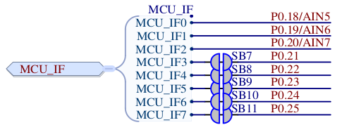
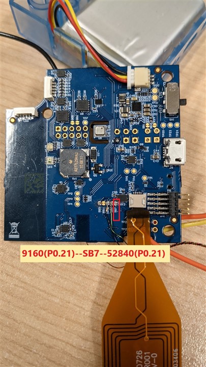
I am trying to configure a GPIO pin P0.21(as this is exposed pin on Thingy:91) from nRF9160 on Thingy:91.
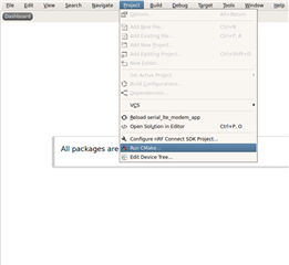
I am using nRF Connect SDK 1.4.1 with Nordic version of SES.
I tried using from zephyr documented here.
#include <drivers/gpio.h>

void main()
{
	gpio = device_get_binding("GPIO_0");
	gpio_pin_configure(gpio, 21, GPIO_OUTPUT_ACTIVE);
	gpio_pin_set(gpio, 21, 1);
}
But I can't see the pin going high after power bootup.
Is there anything I am missing like editing .dts file, because thingy91_nrf9160_common.dts found at \nrf\boards\arm\thingy91_nrf9160 is like this
/*
 * Copyright (c) 2019 Nordic Semiconductor ASA
 *
 * SPDX-License-Identifier: LicenseRef-BSD-5-Clause-Nordic
 */

/ {
	model = "Nordic Thingy91 nRF9160";
	compatible = "nordic,thingy91-nrf9160";

	chosen {
		zephyr,console = &uart0;
		zephyr,shell-uart = &uart0;
		zephyr,uart-mcumgr = &uart0;
	};

	buttons {
		compatible = "gpio-keys";

		button0: button_0 {
			gpios = <&gpio0 26 (GPIO_PULL_UP | GPIO_ACTIVE_LOW)>;
			label = "Button 1";
		};
	};

	leds {
		compatible = "gpio-leds";
		red_led: led_1 {
			gpios = <&gpio0 29 0>;
			label = "RGB red channel";
		};
		green_led: led_2 {
			gpios = <&gpio0 30 0>;
			label = "RGB green channel";
		};
		blue_led: led_3 {
			gpios = <&gpio0 31 0>;
			label = "RGB blue channel";
		};
		sense_red_led: led_4 {
			gpios = <&gpio0 0 0>;
			label = "RGB red channel";
		};
		sense_green_led: led_5 {
			gpios = <&gpio0 1 0>;
			label = "RGB green channel";
		};
		sense_blue_led: led_6 {
			gpios = <&gpio0 2 0>;
			label = "RGB blue channel";
		};
	};

	aliases {
		sw0 = &button0;
		led0 = &red_led;
		led1 = &green_led;
		led2 = &blue_led;
		sense-led0 = &sense_red_led;
		sense-led1 = &sense_green_led;
		sense-led2 = &sense_blue_led;
		rgb-pwm = &pwm0;
		buzzer-pwm = &pwm1;
		nmos-pwm = &pwm2;
	};
};

&adc {
	status = "okay";
};

&gpiote {
	status = "okay";
};

&gpio0 {
	status = "okay";
};

/* PWM0 is intended for RGB LED control */
&pwm0 {
	status = "okay";
	ch0-pin = <29>;
	ch1-pin = <30>;
	ch2-pin = <31>;
};

/* PWM1 is intended for buzzer control */
&pwm1 {
	status = "okay";
	ch0-pin = <28>;
};

/* PWM2 is intended for NMOS transistor control */
&pwm2 {
	status = "okay";
	ch0-pin = <13>;
	ch1-pin = <14>;
	ch2-pin = <15>;
	ch3-pin = <16>;
};

&pwm3 {
	status = "okay";
};

&i2c2 {
	compatible = "nordic,nrf-twim";
	status = "okay";
	sda-pin = <11>;
	scl-pin = <12>;
	clock-frequency = <I2C_BITRATE_FAST>;

	bme680@76 {
		compatible = "bosch,bme680";
		label = "BME680";
		reg = <0x76>;
	};

	bh1749@38 {
			compatible = "rohm,bh1749";
			label = "BH1749";
			reg = <0x38>;
			int-gpios = <&gpio0 27 0>;
	};
};

&spi3 {
	compatible = "nordic,nrf-spim";
	status = "okay";
	sck-pin = <3>;
	mosi-pin = <4>;
	miso-pin = <5>;
	cs-gpios = <&gpio0 8 GPIO_ACTIVE_LOW>, <&gpio0 7 GPIO_ACTIVE_LOW>;

	adxl362@0 {
		compatible = "adi,adxl362";
		label = "ADXL362";
		spi-max-frequency = <8000000>;
		reg = <0>;
		int1-gpios = <&gpio0 9 0>;
	};

	adxl372@1 {
		compatible = "adi,adxl372";
		label = "ADXL372";
		spi-max-frequency = <8000000>;
		reg = <1>;
		int1-gpios = <&gpio0 6 0>;
	};
};

&timer0 {
	status = "okay";
};

&timer1 {
	status = "okay";
};

&timer2 {
	status = "okay";
};

&uart0 {
	compatible = "nordic,nrf-uarte";
	current-speed = <115200>;
	status = "okay";
	tx-pin = <23>;
	rx-pin = <24>;
	rts-pin = <22>;
	cts-pin = <25>;
};

&uart1 {
	current-speed = <1000000>;
	status = "okay";
	tx-pin = <21>;
	rx-pin = <19>;
	rts-pin = <20>;
	cts-pin = <18>;
};

&flash0 {
	/*
	 * For more information, see:
	 * http://docs.zephyrproject.org/devices/dts/flash_partitions.html
	 */
	partitions {
		compatible = "fixed-partitions";
		#address-cells = <1>;
		#size-cells = <1>;

		boot_partition: partition@0 {
			label = "mcuboot";
			reg = <0x00000000 0x10000>;
		};
		slot0_partition: partition@10000 {
			label = "image-0";
		};
		slot0_ns_partition: partition@40000 {
			label = "image-0-nonsecure";
		};
		slot1_partition: partition@80000 {
			label = "image-1";
		};
		slot1_ns_partition: partition@b0000 {
			label = "image-1-nonsecure";
		};
		scratch_partition: partition@f0000 {
			label = "image-scratch";
			reg = <0x000f0000 0xa000>;
		};
		storage_partition: partition@fa000 {
			label = "storage";
			reg = <0x000fa000 0x00006000>;
		};
	};
};

/ {

	reserved-memory {
		#address-cells = <1>;
		#size-cells = <1>;
		ranges;

		sram0_s: image_s@20000000 {
			/* Secure image memory */
		};

		sram0_bsd: image_bsd@20010000 {
			/* BSD (shared) memory */
		};

		sram0_ns: image_ns@20020000 {
			/* Non-Secure image memory */
		};
	};
};

/* Include partition configuration file */
#include "thingy91_nrf9160_partition_conf.dts"
I will appreciate any insight on this.
Thanks!