This post is older than 2 years and might not be relevant anymore
More Info: Consider searching for newer posts

Unable to route to nrf52832 pins in altium designer files

I'm currently working on the nrf52832_qfax_dcdc pcb after adding a few components.  I need to route to pins p0.22, p0.23 SWDIO and SWDCLK but am unable to route away from the original layout.  For reference:

The red square surrounding the nrf52832 just represents a GND copper plate I'm assuming.  And when I try to route off of this red square area I'm unable to do this.  I see the other parts that route over it have gaps in the red square area, but I wasn't sure how to modify this to route off of the area.  Any help with this issue or general advice would be greatly appreciated, thanks!

Update:  There seems to be a clearance boundary surrounding the square as shown below that is stopping me from routing to the 52832.  Is there a way to alter this so that I can route past this?  The same boundary also exists on the bottom layer as well.   I've realized this comes from the keepout layer, and was wondering if it was okay to remove it so that I can route to the 52832.  I assume it is there for a reason but I'm not sure how else to route to the chip.

Parents
  • That is most likely a copper pour.  Look it the "Tools | Polygon Pours | Polygon Manager" and see if you can find it.  If you look at the properties, there is a combo box with options such as  "Pour Over Same Net Polygons Only."  You want to select "Pour Over All Same Net Objects" and then if you route a trace to that polygon with the same net name as the polygon, then repour the polygon and it should connect to the trace.

Reply
  • That is most likely a copper pour.  Look it the "Tools | Polygon Pours | Polygon Manager" and see if you can find it.  If you look at the properties, there is a combo box with options such as  "Pour Over Same Net Polygons Only."  You want to select "Pour Over All Same Net Objects" and then if you route a trace to that polygon with the same net name as the polygon, then repour the polygon and it should connect to the trace.

Children
  • It was a polygon pour and it already is set to "pour over all same net objects".  My issue is routing over the polygon though, not routing to it.  I can route traces over top of the polygon, but the interactive routing doesn't let me route off of the polygon when I try to move outside of its edges.  Do you know what would cause this?

    I also tried just removing the pours but I'm still unable to route past where they were, so now I'm not entirely sure it was related to the  pours.

    When pressing ctwl+w in the interactive routing there seems to be a clearance boundary that surrounds the entire area around the initial reference layout for the nrf52832.  I'm not sure how to remove it though as it seems unrelated to routing or layer boundaries as removing certain layers or routes does not remove the clearance boundary.

  • Sorry, I think I misunderstood the issue you were having.  Are you having trouble routing through that area on other layers or just the layer with the pour?  You might have a thing called a room in that area.  In the properties section, when nothing is selected, you can choose what type of objects you are selecting.  Turn off everything, then select rooms, and then select the area around the part and see if something gets highlighted.  If so, look at the properties and look for the name of the room.  You can look in the rules section and see if any rules exists that are focused on that room.  For instance, here is a snippet from a width rule in a design I'm working on.  Note I'm not an Altium expert, so someone else should chime in if I'm missing the right idea...

  • So I realized that there is actually just a keepout layer that nordic has in their design files.  I think it's just a manufacturing spec as it just outlined the original layout, so when I increased the board size the keepout layer stayed the same and I couldn't route past it.  I was able to just expand the keepout layer to the new board perimeter which let me route to the nrf52832 chip. As long as there aren't any problems with changing the keepout layer I think everything should be fine, and the design rule check passed with no errors so I think things are fine now!  Thanks for the help!

  • Hi Jake,

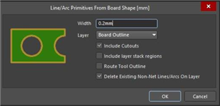
    I am glad to see it seems like you have resolved the issue. One comment I have is that I recommend you redifine the board outline so it follows the PCB shape. You will find this in Design > Board Shape > Create Primitives from Board Shape.

    Same for the keep-out area. Keepout is not really necessary if you choose "Remove Dead copper" in the Polygon settings and add a design rule call "Board outline Clearance".

    Best regards,

    Marjeris

  • Thanks for the extra advice, I'll definitely implement this!

    What are the board outline and keepout areas used for?  When I did the design I just dragged the keepout area so that it matched the outline of the board, but I wasn't sure what it was used for or if there was a more sophisticated way to set them up properly.

Related