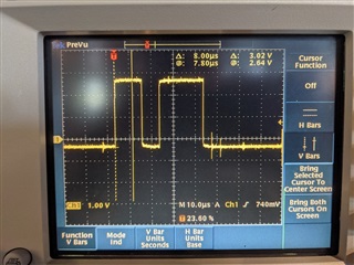
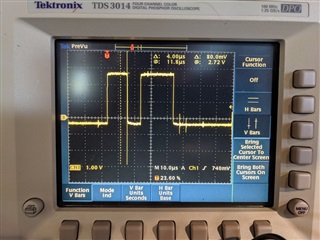
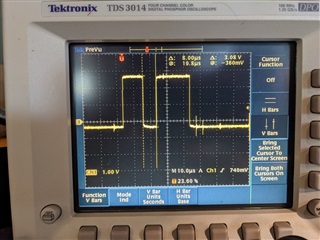
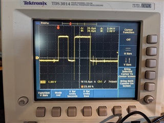
I am having issue configuring the chip select (CS) in my little test program. I have read through the SPI drivers and debugged through it and from what I can tell I have everything setup right. I am also monitoring the CS signal on a scope to watch for it to go low (active low). Even after the SPI init/config routine runs I never see my CS pin go high.
What am I missing?
main.c :
/*
* Copyright (c) 2016 Intel Corporation
*
* SPDX-License-Identifier: Apache-2.0
*/
#include <errno.h>
#include <zephyr.h>
#include <sys/printk.h>
#include <device.h>
#include <drivers/spi.h>
/**
* @file Sample app using the Cypress CY15B102QN (driver based on Fujitsu MB85RS64V) FRAM through SPI.
*/
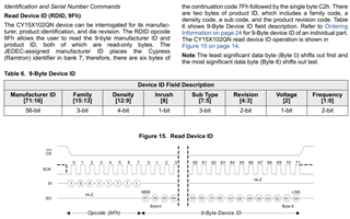
#define CY15B102QN_MANUFACTURER_ID_CMD 0x9f
#define CY15B102QN_WRITE_ENABLE_CMD 0x06
#define CY15B102QN_READ_CMD 0x03
#define CY15B102QN_WRITE_CMD 0x02
#define MAX_USER_DATA_LENGTH 1024
#define SPI_DEV DT_LABEL(DT_NODELABEL(spi1))
static uint8_t data[MAX_USER_DATA_LENGTH], cmp_data[MAX_USER_DATA_LENGTH];
static int cy15b102qn_access(const struct device *spi,
struct spi_config *spi_cfg,
uint8_t cmd, uint16_t addr, void *data, size_t len)
{
uint8_t access[3];
struct spi_buf bufs[] = {
{
.buf = access,
},
{
.buf = data,
.len = len
}
};
struct spi_buf_set tx = {
.buffers = bufs
};
access[0] = cmd;
if (cmd == CY15B102QN_WRITE_CMD || cmd == CY15B102QN_READ_CMD) {
access[1] = (addr >> 8) & 0xFF;
access[2] = addr & 0xFF;
bufs[0].len = 3;
tx.count = 2;
if (cmd == CY15B102QN_READ_CMD) {
struct spi_buf_set rx = {
.buffers = bufs,
.count = 2
};
return spi_transceive(spi, spi_cfg, &tx, &rx);
}
} else {
tx.count = 1;
}
return spi_write(spi, spi_cfg, &tx);
}
static int cy15b102qn_read_id(const struct device *spi,
struct spi_config *spi_cfg)
{
uint8_t id[4];
int err;
err = cy15b102qn_access(spi, spi_cfg,
CY15B102QN_MANUFACTURER_ID_CMD, 0, &id, 4);
if (err) {
printk("Error during ID read\n");
return -EIO;
}
/*
if (id[0] != 0x04) {
return -EIO;
}
if (id[1] != 0x7f) {
return -EIO;
}
if (id[2] != 0x03) {
return -EIO;
}
if (id[3] != 0x02) {
return -EIO;
}
*/
return 0;
}
static int write_bytes(const struct device *spi, struct spi_config *spi_cfg,
uint16_t addr, uint8_t *data, uint32_t num_bytes)
{
int err;
/* disable write protect */
err = cy15b102qn_access(spi, spi_cfg,
CY15B102QN_WRITE_ENABLE_CMD, 0, NULL, 0);
if (err) {
printk("unable to disable write protect\n");
return -EIO;
}
/* write cmd */
err = cy15b102qn_access(spi, spi_cfg,
CY15B102QN_WRITE_CMD, addr, data, num_bytes);
if (err) {
printk("Error during SPI write\n");
return -EIO;
}
return 0;
}
static int read_bytes(const struct device *spi, struct spi_config *spi_cfg,
uint16_t addr, uint8_t *data, uint32_t num_bytes)
{
int err;
/* read cmd */
err = cy15b102qn_access(spi, spi_cfg,
CY15B102QN_READ_CMD, addr, data, num_bytes);
if (err) {
printk("Error during SPI read\n");
return -EIO;
}
return 0;
}
void main(void)
{
const struct device *spi;
struct spi_config spi_cfg = {0};
printk("fujitsu FRAM example application\n");
spi = device_get_binding(SPI_DEV);
if (!spi) {
printk("Could not find SPI driver\n");
return;
}
int err;
//Setup chip select struct / config
struct spi_cs_control cs_cfg = {
.gpio_dev = spi,
.delay = 10,
.gpio_pin = 20,
.gpio_dt_flags = GPIO_ACTIVE_LOW,
};
spi_cfg.cs = &cs_cfg;
spi_cfg.operation = SPI_WORD_SET(8);
//Sets frequency!
spi_cfg.frequency = 256000U;
err = cy15b102qn_read_id(spi, &spi_cfg);
if (err) {
printk("Could not verify FRAM ID\n");
return;
}
/* Do one-byte read/write */
data[0] = 0xAE;
err = write_bytes(spi, &spi_cfg, 0x00, data, 1);
if (err) {
printk("Error writing to FRAM! errro code (%d)\n", err);
return;
} else {
printk("Wrote 0xAE to address 0x00.\n");
}
data[0] = 0x86;
err = write_bytes(spi, &spi_cfg, 0x01, data, 1);
if (err) {
printk("Error writing to FRAM! error code (%d)\n", err);
return;
} else {
printk("Wrote 0x86 to address 0x01.\n");
}
data[0] = 0x00;
err = read_bytes(spi, &spi_cfg, 0x00, data, 1);
if (err) {
printk("Error reading from FRAM! error code (%d)\n", err);
return;
} else {
printk("Read 0x%X from address 0x00.\n", data[0]);
}
data[0] = 0x00;
err = read_bytes(spi, &spi_cfg, 0x01, data, 1);
if (err) {
printk("Error reading from FRAM! error code (%d)\n", err);
return;
} else {
printk("Read 0x%X from address 0x01.\n", data[0]);
}
/* Do multi-byte read/write */
/* get some random data, and clear out data[] */
for (uint32_t i = 0; i < sizeof(cmp_data); i++) {
cmp_data[i] = k_cycle_get_32() & 0xFF;
data[i] = 0x00;
}
/* write them to the FRAM */
err = write_bytes(spi, &spi_cfg, 0x00, cmp_data, sizeof(cmp_data));
if (err) {
printk("Error writing to FRAM! error code (%d)\n", err);
return;
} else {
printk("Wrote %d bytes to address 0x00.\n",
(uint32_t) sizeof(cmp_data));
}
err = read_bytes(spi, &spi_cfg, 0x00, data, sizeof(data));
if (err) {
printk("Error reading from FRAM! error code (%d)\n", err);
return;
} else {
printk("Read %d bytes from address 0x00.\n",
(uint32_t) sizeof(data));
}
err = 0;
for (uint32_t i = 0; i < sizeof(cmp_data); i++) {
if (cmp_data[i] != data[i]) {
printk("Data comparison failed @ %d.\n", i);
err = -EIO;
}
}
if (err == 0) {
printk("Data comparison successful.\n");
}
}
nrf52833dk_nrf52833.overlay :
&spi1 {
	compatible = "nordic,nrf-spim";
	status = "okay";

	mosi-pin = <23>;
	miso-pin = <22>;
	sck-pin = <21>;
	clock-frequency = <4000000>;

	//cs-gpios = <&gpio0 20 GPIO_ACTIVE_LOW>;
	spi-device@0 {
                  reg = <0>;
                  label = "CY15B102QN";
				  //cs-gpios = <&gpio0 20 GPIO_ACTIVE_LOW>;
          };


	//spi-max-frequency = <4000000>;
};

&spi2 {
	status = "disabled";
};

&i2c1 {
    status = "disabled";
};
prj.conf :
CONFIG_STDOUT_CONSOLE=y
CONFIG_PRINTK=y

CONFIG_SPI=y
#CONFIG_SPI_1=y
#CONFIG_SPI_NRFX=y

CONFIG_GPIO=y

CONFIG_MAIN_STACK_SIZE=4096
zephyr.dts :
/dts-v1/;

/ {
	#address-cells = < 0x1 >;
	#size-cells = < 0x1 >;
	model = "Nordic nRF52833 DK NRF52833";
	compatible = "nordic,nrf52833-dk-nrf52833";
	chosen {
		zephyr,entropy = &rng;
		zephyr,flash-controller = &flash_controller;
		zephyr,console = &uart0;
		zephyr,shell-uart = &uart0;
		zephyr,uart-mcumgr = &uart0;
		zephyr,bt-mon-uart = &uart0;
		zephyr,bt-c2h-uart = &uart0;
		zephyr,sram = &sram0;
		zephyr,flash = &flash0;
		zephyr,code-partition = &slot0_partition;
	};
	aliases {
		led0 = &led0;
		led1 = &led1;
		led2 = &led2;
		led3 = &led3;
		pwm-led0 = &pwm_led0;
		sw0 = &button0;
		sw1 = &button1;
		sw2 = &button2;
		sw3 = &button3;
	};
	soc {
		#address-cells = < 0x1 >;
		#size-cells = < 0x1 >;
		compatible = "nordic,nRF52833-QIAA", "nordic,nRF52833", "nordic,nRF52", "simple-bus";
		interrupt-parent = < &nvic >;
		ranges;
		nvic: interrupt-controller@e000e100 {
			compatible = "arm,v7m-nvic";
			reg = < 0xe000e100 0xc00 >;
			interrupt-controller;
			#interrupt-cells = < 0x2 >;
			arm,num-irq-priority-bits = < 0x3 >;
			phandle = < 0x1 >;
		};
		systick: timer@e000e010 {
			compatible = "arm,armv7m-systick";
			reg = < 0xe000e010 0x10 >;
			status = "disabled";
		};
		flash_controller: flash-controller@4001e000 {
			compatible = "nordic,nrf52-flash-controller";
			reg = < 0x4001e000 0x1000 >;
			#address-cells = < 0x1 >;
			#size-cells = < 0x1 >;
			label = "NRF_FLASH_DRV_NAME";
			flash0: flash@0 {
				compatible = "soc-nv-flash";
				label = "NRF_FLASH";
				erase-block-size = < 0x1000 >;
				write-block-size = < 0x4 >;
				reg = < 0x0 0x80000 >;
				partitions {
					compatible = "fixed-partitions";
					#address-cells = < 0x1 >;
					#size-cells = < 0x1 >;
					boot_partition: partition@0 {
						label = "mcuboot";
						reg = < 0x0 0xc000 >;
					};
					slot0_partition: partition@c000 {
						label = "image-0";
						reg = < 0xc000 0x32000 >;
					};
					slot1_partition: partition@3e000 {
						label = "image-1";
						reg = < 0x3e000 0x32000 >;
					};
					scratch_partition: partition@70000 {
						label = "image-scratch";
						reg = < 0x70000 0xa000 >;
					};
					storage_partition: partition@7a000 {
						label = "storage";
						reg = < 0x7a000 0x6000 >;
					};
				};
			};
		};
		sram0: memory@20000000 {
			compatible = "mmio-sram";
			reg = < 0x20000000 0x20000 >;
		};
		adc: adc@40007000 {
			compatible = "nordic,nrf-saadc";
			reg = < 0x40007000 0x1000 >;
			interrupts = < 0x7 0x1 >;
			status = "okay";
			label = "ADC_0";
			#io-channel-cells = < 0x1 >;
		};
		clock: clock@40000000 {
			compatible = "nordic,nrf-clock";
			reg = < 0x40000000 0x1000 >;
			interrupts = < 0x0 0x1 >;
			status = "okay";
			label = "CLOCK";
		};
		ecb: ecb@4000e000 {
			compatible = "nordic,nrf-ecb";
			reg = < 0x4000e000 0x1000 >;
			interrupts = < 0xe 0x1 >;
			status = "okay";
			label = "ECB";
		};
		uart0: uart@40002000 {
			reg = < 0x40002000 0x1000 >;
			interrupts = < 0x2 0x1 >;
			status = "okay";
			label = "UART_0";
			compatible = "nordic,nrf-uarte";
			current-speed = < 0x1c200 >;
			tx-pin = < 0x6 >;
			rx-pin = < 0x8 >;
			rts-pin = < 0x5 >;
			cts-pin = < 0x7 >;
		};
		uart1: arduino_serial: uart@40028000 {
			compatible = "nordic,nrf-uarte";
			reg = < 0x40028000 0x1000 >;
			interrupts = < 0x28 0x1 >;
			status = "okay";
			label = "UART_1";
			current-speed = < 0x1c200 >;
			rx-pin = < 0x21 >;
			tx-pin = < 0x22 >;
		};
		gpiote: gpiote@40006000 {
			compatible = "nordic,nrf-gpiote";
			reg = < 0x40006000 0x1000 >;
			interrupts = < 0x6 0x5 >;
			status = "okay";
			label = "GPIOTE_0";
		};
		gpio0: gpio@50000000 {
			compatible = "nordic,nrf-gpio";
			gpio-controller;
			reg = < 0x50000000 0x200 0x50000500 0x300 >;
			#gpio-cells = < 0x2 >;
			label = "GPIO_0";
			status = "okay";
			port = < 0x0 >;
			phandle = < 0x4 >;
		};
		gpio1: gpio@50000300 {
			compatible = "nordic,nrf-gpio";
			gpio-controller;
			reg = < 0x50000300 0x200 0x50000800 0x300 >;
			#gpio-cells = < 0x2 >;
			ngpios = < 0xa >;
			label = "GPIO_1";
			status = "okay";
			port = < 0x1 >;
			phandle = < 0x6 >;
		};
		i2c0: arduino_i2c: i2c@40003000 {
			#address-cells = < 0x1 >;
			#size-cells = < 0x0 >;
			reg = < 0x40003000 0x1000 >;
			clock-frequency = < 0x186a0 >;
			interrupts = < 0x3 0x1 >;
			status = "okay";
			label = "I2C_0";
			compatible = "nordic,nrf-twi";
			sda-pin = < 0x1a >;
			scl-pin = < 0x1b >;
		};
		i2c1: i2c@40004000 {
			#address-cells = < 0x1 >;
			#size-cells = < 0x0 >;
			reg = < 0x40004000 0x1000 >;
			clock-frequency = < 0x186a0 >;
			interrupts = < 0x4 0x1 >;
			status = "disabled";
			label = "I2C_1";
			compatible = "nordic,nrf-twi";
			sda-pin = < 0x1e >;
			scl-pin = < 0x1f >;
		};
		pwm0: pwm@4001c000 {
			compatible = "nordic,nrf-pwm";
			reg = < 0x4001c000 0x1000 >;
			interrupts = < 0x1c 0x1 >;
			status = "okay";
			label = "PWM_0";
			#pwm-cells = < 0x1 >;
			ch0-pin = < 0xd >;
			ch0-inverted;
			phandle = < 0x5 >;
		};
		pwm1: pwm@40021000 {
			compatible = "nordic,nrf-pwm";
			reg = < 0x40021000 0x1000 >;
			interrupts = < 0x21 0x1 >;
			status = "disabled";
			label = "PWM_1";
			#pwm-cells = < 0x1 >;
		};
		pwm2: pwm@40022000 {
			compatible = "nordic,nrf-pwm";
			reg = < 0x40022000 0x1000 >;
			interrupts = < 0x22 0x1 >;
			status = "disabled";
			label = "PWM_2";
			#pwm-cells = < 0x1 >;
		};
		pwm3: pwm@4002d000 {
			compatible = "nordic,nrf-pwm";
			reg = < 0x4002d000 0x1000 >;
			interrupts = < 0x2d 0x1 >;
			status = "disabled";
			label = "PWM_3";
			#pwm-cells = < 0x1 >;
		};
		qdec: qdec@40012000 {
			compatible = "nordic,nrf-qdec";
			reg = < 0x40012000 0x1000 >;
			interrupts = < 0x12 0x1 >;
			status = "disabled";
			label = "QDEC";
		};
		rng: random@4000d000 {
			compatible = "nordic,nrf-rng";
			reg = < 0x4000d000 0x1000 >;
			interrupts = < 0xd 0x1 >;
			status = "okay";
			label = "RNG";
		};
		spi0: spi@40003000 {
			#address-cells = < 0x1 >;
			#size-cells = < 0x0 >;
			reg = < 0x40003000 0x1000 >;
			interrupts = < 0x3 0x1 >;
			status = "disabled";
			label = "SPI_0";
			compatible = "nordic,nrf-spi";
			sck-pin = < 0x1b >;
			mosi-pin = < 0x1a >;
			miso-pin = < 0x1d >;
		};
		spi1: spi@40004000 {
			#address-cells = < 0x1 >;
			#size-cells = < 0x0 >;
			reg = < 0x40004000 0x1000 >;
			interrupts = < 0x4 0x1 >;
			status = "okay";
			label = "SPI_1";
			compatible = "nordic,nrf-spim";
			sck-pin = < 0x15 >;
			mosi-pin = < 0x17 >;
			miso-pin = < 0x16 >;
			clock-frequency = < 0x3d0900 >;
			spi-device@0 {
				reg = < 0x0 >;
				label = "CY15B102QN";
			};
		};
		spi2: spi@40023000 {
			#address-cells = < 0x1 >;
			#size-cells = < 0x0 >;
			reg = < 0x40023000 0x1000 >;
			interrupts = < 0x23 0x1 >;
			status = "disabled";
			label = "SPI_2";
		};
		spi3: arduino_spi: spi@4002f000 {
			compatible = "nordic,nrf-spim";
			#address-cells = < 0x1 >;
			#size-cells = < 0x0 >;
			reg = < 0x4002f000 0x1000 >;
			interrupts = < 0x2f 0x1 >;
			status = "okay";
			label = "SPI_3";
			sck-pin = < 0x17 >;
			miso-pin = < 0x16 >;
			mosi-pin = < 0x15 >;
			cs-gpios = < &arduino_header 0x10 0x1 >;
		};
		rtc0: rtc@4000b000 {
			compatible = "nordic,nrf-rtc";
			reg = < 0x4000b000 0x1000 >;
			cc-num = < 0x3 >;
			interrupts = < 0xb 0x1 >;
			status = "okay";
			clock-frequency = < 0x8000 >;
			prescaler = < 0x1 >;
			label = "RTC_0";
		};
		rtc1: rtc@40011000 {
			compatible = "nordic,nrf-rtc";
			reg = < 0x40011000 0x1000 >;
			cc-num = < 0x4 >;
			interrupts = < 0x11 0x1 >;
			status = "okay";
			clock-frequency = < 0x8000 >;
			prescaler = < 0x1 >;
			label = "RTC_1";
		};
		rtc2: rtc@40024000 {
			compatible = "nordic,nrf-rtc";
			reg = < 0x40024000 0x1000 >;
			cc-num = < 0x4 >;
			interrupts = < 0x24 0x1 >;
			status = "okay";
			clock-frequency = < 0x8000 >;
			prescaler = < 0x1 >;
			label = "RTC_2";
		};
		timer0: timer@40008000 {
			compatible = "nordic,nrf-timer";
			status = "okay";
			reg = < 0x40008000 0x1000 >;
			cc-num = < 0x4 >;
			interrupts = < 0x8 0x1 >;
			prescaler = < 0x0 >;
			label = "TIMER_0";
		};
		timer1: timer@40009000 {
			compatible = "nordic,nrf-timer";
			status = "okay";
			reg = < 0x40009000 0x1000 >;
			cc-num = < 0x4 >;
			interrupts = < 0x9 0x1 >;
			prescaler = < 0x0 >;
			label = "TIMER_1";
		};
		timer2: timer@4000a000 {
			compatible = "nordic,nrf-timer";
			status = "okay";
			reg = < 0x4000a000 0x1000 >;
			cc-num = < 0x4 >;
			interrupts = < 0xa 0x1 >;
			prescaler = < 0x0 >;
			label = "TIMER_2";
			phandle = < 0x3 >;
		};
		timer3: timer@4001a000 {
			compatible = "nordic,nrf-timer";
			status = "okay";
			reg = < 0x4001a000 0x1000 >;
			cc-num = < 0x6 >;
			interrupts = < 0x1a 0x1 >;
			prescaler = < 0x0 >;
			label = "TIMER_3";
		};
		timer4: timer@4001b000 {
			compatible = "nordic,nrf-timer";
			status = "okay";
			reg = < 0x4001b000 0x1000 >;
			cc-num = < 0x6 >;
			interrupts = < 0x1b 0x1 >;
			prescaler = < 0x0 >;
			label = "TIMER_4";
		};
		temp: temp@4000c000 {
			compatible = "nordic,nrf-temp";
			reg = < 0x4000c000 0x1000 >;
			interrupts = < 0xc 0x1 >;
			status = "okay";
			label = "TEMP_0";
		};
		usbd: usbd@40027000 {
			compatible = "nordic,nrf-usbd";
			reg = < 0x40027000 0x1000 >;
			interrupts = < 0x27 0x1 >;
			num-bidir-endpoints = < 0x1 >;
			num-in-endpoints = < 0x7 >;
			num-out-endpoints = < 0x7 >;
			num-isoin-endpoints = < 0x1 >;
			num-isoout-endpoints = < 0x1 >;
			status = "okay";
			label = "USBD";
		};
		wdt: wdt0: watchdog@40010000 {
			compatible = "nordic,nrf-watchdog";
			reg = < 0x40010000 0x1000 >;
			interrupts = < 0x10 0x1 >;
			status = "okay";
			label = "WDT";
		};
		ficr: ficr@10000000 {
			compatible = "nordic,nrf-ficr";
			reg = < 0x10000000 0x1000 >;
			status = "okay";
		};
		uicr: uicr@10001000 {
			compatible = "nordic,nrf-uicr";
			reg = < 0x10001000 0x1000 >;
			status = "okay";
		};
		radio: radio@40001000 {
			compatible = "nordic,nrf-radio";
			reg = < 0x40001000 0x1000 >;
			interrupts = < 0x1 0x1 >;
			status = "okay";
			dfe-ant-num = < 0x0 >;
		};
	};
	cpus {
		#address-cells = < 0x1 >;
		#size-cells = < 0x0 >;
		cpu@0 {
			device_type = "cpu";
			compatible = "arm,cortex-m4f";
			reg = < 0x0 >;
		};
	};
	sw_pwm: sw-pwm {
		compatible = "nordic,nrf-sw-pwm";
		status = "disabled";
		label = "SW_PWM";
		generator = < &timer2 >;
		channel-count = < 0x3 >;
		clock-prescaler = < 0x0 >;
		ppi-base = < 0x0 >;
		gpiote-base = < 0x0 >;
		#pwm-cells = < 0x1 >;
	};
	leds {
		compatible = "gpio-leds";
		led0: led_0 {
			gpios = < &gpio0 0xd 0x1 >;
			label = "Green LED 0";
		};
		led1: led_1 {
			gpios = < &gpio0 0xe 0x1 >;
			label = "Green LED 1";
		};
		led2: led_2 {
			gpios = < &gpio0 0xf 0x1 >;
			label = "Green LED 2";
		};
		led3: led_3 {
			gpios = < &gpio0 0x10 0x1 >;
			label = "Green LED 3";
		};
	};
	pwmleds {
		compatible = "pwm-leds";
		pwm_led0: pwm_led_0 {
			pwms = < &pwm0 0xd >;
		};
	};
	buttons {
		compatible = "gpio-keys";
		button0: button_0 {
			gpios = < &gpio0 0xb 0x11 >;
			label = "Push button switch 0";
		};
		button1: button_1 {
			gpios = < &gpio0 0xc 0x11 >;
			label = "Push button switch 1";
		};
		button2: button_2 {
			gpios = < &gpio0 0x18 0x11 >;
			label = "Push button switch 2";
		};
		button3: button_3 {
			gpios = < &gpio0 0x19 0x11 >;
			label = "Push button switch 3";
		};
	};
	arduino_header: connector {
		compatible = "arduino-header-r3";
		#gpio-cells = < 0x2 >;
		gpio-map-mask = < 0xffffffff 0xffffffc0 >;
		gpio-map-pass-thru = < 0x0 0x3f >;
		gpio-map = < 0x0 0x0 &gpio0 0x3 0x0 >, < 0x1 0x0 &gpio0 0x4 0x0 >, < 0x2 0x0 &gpio0 0x1c 0x0 >, < 0x3 0x0 &gpio0 0x1d 0x0 >, < 0x4 0x0 &gpio0 0x1e 0x0 >, < 0x5 0x0 &gpio0 0x1f 0x0 >, < 0x6 0x0 &gpio1 0x1 0x0 >, < 0x7 0x0 &gpio1 0x2 0x0 >, < 0x8 0x0 &gpio1 0x3 0x0 >, < 0x9 0x0 &gpio1 0x4 0x0 >, < 0xa 0x0 &gpio1 0x5 0x0 >, < 0xb 0x0 &gpio1 0x6 0x0 >, < 0xc 0x0 &gpio1 0x7 0x0 >, < 0xd 0x0 &gpio1 0x8 0x0 >, < 0xe 0x0 &gpio0 0x11 0x0 >, < 0xf 0x0 &gpio0 0x13 0x0 >, < 0x10 0x0 &gpio0 0x14 0x0 >, < 0x11 0x0 &gpio0 0x15 0x0 >, < 0x12 0x0 &gpio0 0x16 0x0 >, < 0x13 0x0 &gpio0 0x17 0x0 >, < 0x14 0x0 &gpio0 0x1a 0x0 >, < 0x15 0x0 &gpio0 0x1b 0x0 >;
		phandle = < 0x2 >;
	};
};
CMakeLists.txt :
# SPDX-License-Identifier: Apache-2.0

set(TEST_DTC_OVERLAY_FILE
  ${CMAKE_CURRENT_SOURCE_DIR}/nrf52833dk_nrf52833.overlay
)

set(PRJ_CONF_FILE
  prj.conf
  ${CMAKE_CURRENT_LIST_DIR}/prj.conf
)

cmake_minimum_required(VERSION 3.13.1)
find_package(Zephyr REQUIRED HINTS $ENV{ZEPHYR_BASE})
project(spi_fujitsu_fram)

FILE(GLOB app_sources src/*.c)
target_sources(app PRIVATE ${app_sources})
SDK: nRF Connect SDK v1.5.1