This post is older than 2 years and might not be relevant anymore
More Info: Consider searching for newer posts

Unexpected behaviour with PPK2 logic inputs & Logic Port VCC pin

I'm more of a programmer than an electronics person so I apologise in advance if I misuse terminology or if the answer to this would be obvious if I had more experience.

I have just received a PPK2 and I wanted to profile a "TZT Mini PIR Motion Human Sensor Automatic Detector Module AM312 Sensor".

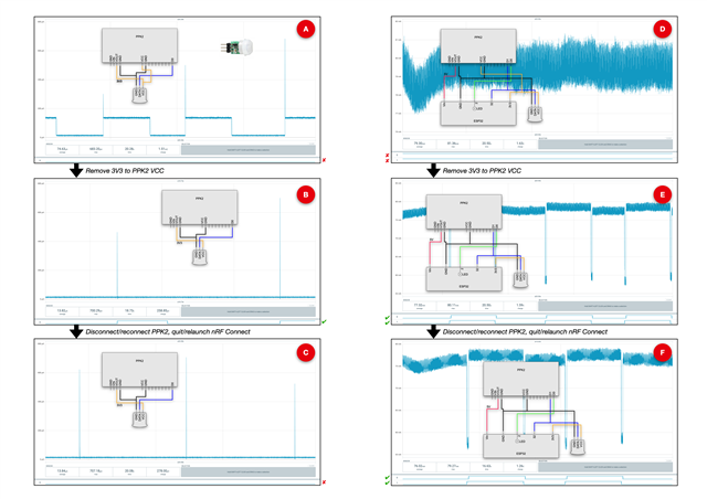
I connected everything as shown in "A". That hookup was based on my reading of section "6.4 Logic port" of the PPK2_User_Guide_v1.0.1.pdf.

I put the PPK2 in "Source meter" mode and set the supply voltage to 3300mv. I enabled D0 and power output, started a capture and triggered the PIR sensor. The trace was as shown in "A". In the un-triggered state, the DUT consumed 14μA. When triggered it spiked briefly then settled to 136μA. However, the D0 trace did not go HIGH to show the DUT going active.

After trying a different logic port (no difference), I decided to disconnect the VCC-VCC lead, as per "B", and try again. This time D0 went HIGH each time I triggered the DUT, going LOW again after ~3 seconds. The current spiked when the DUT was triggered but, apart from the spike, consumption remained at 14μA throughout. I think of this as the expected behaviour.

(I have conducted the same test with a bench power supply set to 3.3v, a μCurrentGold, and an oscilloscope. The result is similar to "B". I can see the PIR DATA line go high but, apart from a brief spike, current consumption is the same whether the PIR is triggered or not. So I have some confidence that the traces in "B" are correct.)

Without changing the wiring, I:

1. Quit nRF Connect.
2. Turned the PPK2 off and on again.
3. Started nRF Connect again.
4. Repeated the test.

The result is shown in "C". This time the the spikes appeared each time I triggered the DUT, the consumption remained at 14μA, but the D0 trace did not go HIGH to show the DUT going active. It is sort of a hybrid of "A" (no D0 trace) and "B" (spikes on transition but otherwise 14μA throughout).

I have repeated this cycle several times and the result is always the same. The first time power is applied to the circuit, D0 will not follow the PIR signal until VCC has been connected, then disconnected.

My second set of tests used an ESP32 development board. GPIO32 was connected to the PIR data line. GPIO2 is the on-board LED which illuminates when HIGH. A small sketch (attached) running on the board:

1. Initialises during setup() by reading the state of GPIO32 and conforms GPIO2 to the same state as GPIO32.
2. Runs a loop() which senses when GPIO32 changes state, waits 100ms, and then conforms GPIO2 to that state observed for GPIO32.

The overall pattern is similar, but not identical, to the first set of tests. Unlike "A", "D" does not show any reaction to the PIR being triggered. Neither does the ESP32 board (the on-board LED does not change). "E" and "F" both show the expected pattern.

Not shown is another test. My starting point was "D" (ie 3v3 VCC reference connected). I disabled power output from the PPK2, disconnected the 3V3 VCC line, started a trace and then enabled power output from the PPK2, The D0 trace (the onboard LED) starts and remains HIGH, while the D1 trace (the PIR) starts and remains LOW. What actually happens on the board is that the LED turns on then off. This is because the startup() code reads the state of GPIO32 (the PIR) and sets GPIO2 (the LED) to be the same. In other words, the ESP32 thinks the PIR is triggered - yet the PPK2 D1 trace suggests it is not. When I subsequently trigger the PIR, the current trace is as per "E" and "F" but D0 remains HIGH and D1 remains LOW. On the board, the LED turns on, then off again after ~seconds, indicating that the board is receiving transitions from the PIR. Those transitions are just not making it to the PPK2.


The documentation says DUT VCC should be connected to the PPK2. I assumed that VCC was providing a voltage reference for logic-level shifting. I don't understand why I don't get sensible results from the logic inputs when VCC is connected, nor why VCC needs to be connected and then disconnected before the logic inputs will behave sensibly.

Any ideas?

 NodeMCU32S_PIRTest.ino

  • "The first time power is applied to the circuit, D0 will not follow the PIR signal until VCC has been connected, then disconnected"

    "My starting point was "D" (ie 3v3 VCC reference connected). I disabled power output from the PPK2, disconnected the 3V3 VCC line, started a trace and then enabled power output from the PPK2"

    This will latch up the internal nRF52840 in the PPK2 due to phantom power from the D0 pin when high via the internal schottky diode in nRF52840 on the PPK2, and give the results you are getting.

    Normally there would be only a single voltage supply, the Vout on the PPK2 which must power all connected devices, in other words the PIR should not have a separate supply but share the DUT supply. If you must use a separate supply to the PIR from the DUT, then the power sequence below must be followed:

    1. Remove power from PIR, wait
    2. Remove power from DUT by turning off PPK2 source power, wait
    3. Apply power to DUT by turning on PPK2 source power
    4. Apply power to PIR by turning on PIR VCC power

    Much simpler to just power everything from PPK2 Vout.

  • I don't think I was sufficiently clear. The PPK2 was the only source of power to the device under test. The PIR does not have an independent source of power. The ESP32 board does not have an independent source of power. The hookup is exactly as shown in the diagrams. There are no other power sources that I neglected to show.

    In cases "A", "B" and "C", the PPK2 was sending 3.3V to the PIR sensor. In cases "D", "E", "F" and the final example where I did not provide a diagram, the PPK2 was sending 5V to the ESP32 development board. The dev board has a regulator which takes that 5V input and supplies 3.3V to the ESP32 and the PIR.

    To put this another way, if the "Enable power output" button in nRF Connect is OFF, the entire DUT dies. 

    The "VCC to VCC" line is referring to the reference voltage from the DUT to the PPK2 so that the logic-level shifter can determine what voltage the logic lines are operating at. At least, that's my understanding. In the block diagram on page 9 of PPK2_User_Guide_v1.0.1.pdf, the "Level Shifter" is shown as a separate functional unit that communicates with the SoC. On page 2 of PCA63100_Schematic_And_PCB.pdf, all the lines associated with the logic port are shown as going straight into the nRF52840 (ie no separate circuitry) and the "VCC" on the silk screen is designated "EN" which I take to mean "enable".

    Does this change your answer, or am I missing your point?

  • Ah, I totally misunderstood. Still puzzled though, since graph A looks ok to me except for the increased current. The internal level shifter bus hold feature can draw that much current on a single input, but that implies something fishy about the D0 source.

    So yes the Vcc-Vcc connection is required; maybe enable the digital trace only after turning on Vcc in source mode to see if that helps. I use the digital trace and don't recall any issues, but can try tomorrow ..

  • I've done some more experimentation and I think I might be closing-in on the basic problem.

    The PIR sensor has an onboard voltage regulator with the package marking "HT30", which appears to mean it is 3.0V output.

    My hypothesis was that the 3.3V reference voltage being sent to VCC on the PPK2 logic port was "too high" with respect to the ~3V coming from the PIR's data line.

    To test that theory I fed the ESP32's 3V3-out through a voltage divider to try to match what the PIR was delivering, and sent that to the VCC on the PPK2 logic port.

    The result was that nothing worked. The PPK2 D0 and D1 ports were unable to display logic signals from either the ESP32 onboard LED (3.3V) or the PIR (~3V), irrespective of whether the VCC line was connected or detached.

    My new working theory is that the PPK2 expects 3.3V or nothing. The range given for the logic port VCC in Table 6 on page 18 of the manual is 1.65V through 5.5V so maybe this generalises to "1.8 or 3.3 or 5.0 or nothing". I haven't tried to test that.

    The "connect the 3.3V reference VCC, apply power, remove the reference VCC, measure" trick is a workaround that "works". Of course, to take advantage this workaround, you first have to "know" when you have a peripheral that is sending less voltage than the PPK2 expects. Until that particular penny drops, you're staring at a flatline logic trace and scratching your head.

    To try to put the PPK2 behaviour in context, the ESP32 has no trouble deciding that the PIR has taken the pin HIGH at the lower voltage. Similarly, the Logic 16 + Logic 2 app has no trouble displaying the PIR logic levels. I hesitate to draw too many conclusions from a 2:1 split but the PPK2 does look a bit like the odd guy out.

Related