This post is older than 2 years and might not be relevant anymore
More Info: Consider searching for newer posts

How to flash the leds with a duty cycle that does not equal 50%?

Hello,

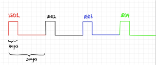
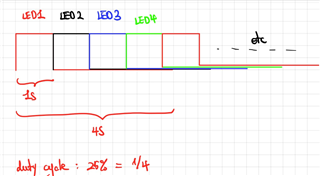
I use the nrf5340 pdk. I would like to flash the led1 with a duty cycle which is different from 50%, so i tried to open the binky_pwm project, but the segger shows that there is error.

So, I look on the forum and I find that there are people who have encountered the same problem and it has solved it well. So I follow the same steps, but it's still wrong for me. (ps: https://devzone.nordicsemi.com/f/nordic-q-a/71402/i-am-looking-for-simple-example-of-hw-driver-of-qdec-for-nrf5340)

So I would like to ask if you have any ideas on this?

Or can you give me a simpler example to achieve my goal? (for example: time on equals 2ms and time off equals 1ms.)

Thank you in advance!

Parents
  • Hi,

    If you want a simpler example, which works out of the box, try the blinky example.

    There you can make a few simple changes to achieve what you are looking for.

    At the top make two different times:

    /* 1000 msec = 1 sec */
    #define ON_TIME_MS      2000
    #define OFF_TIME_MS     1000

    In the while loop, alternate between the times:

    	while (1) {
    		gpio_pin_set(dev, PIN, (int)led_is_on);
    		led_is_on = false;
    		k_msleep(ON_TIME_MS);
    		gpio_pin_set(dev, PIN, (int)led_is_on);
    		led_is_on = true;
    		k_msleep(OFF_TIME_MS);
    	}

  • Hello, thank you for the example.

    In fact, I successfully ran the example binky_pwm, so I would like to ask if you know how to set a pwm_ledext1 at pin1.00 because I set an external led at PIN1.00 through the file nrf5340pdk_nrf5340_cpuapp.overlay.

     {
    	aliases {
    		pwm-led0 = &pwm_led0;
                    pwm-ledext1 = &pwm_ledext1;
                    ledext1 = &ledext1;
    	};
    };
    
    / {
    pwmleds {
    	compatible = "pwm-leds";
    	pwm_led0: pwm_led_0 {
    		pwms = < &pwm0 0x1c >;
    	};
            pwm_ledext1: pwm_led_ext1 {
    		pwms = < &pwm0 0x1c >;
    	};
    };
    };
    
    / {
    leds {
          compatible = "gpio-leds";
          ledext1: led_ext1 {
    		gpios = <&gpio1 00 GPIO_ACTIVE_LOW>;
    		label = "LED EXTERNE 1";
          };
    };
    };

    Thank you in advance!

  • Sorry to bother you again.

    I want to connect led1 and external led with PWM0 to run same frequency.

    In this regard, I set the ch0-pin to 28 followed by led1, then I set the ch1-pin to 32 for the external led.

    &pwm0 {
              ch0-pin = <28>;
              ch1-pin = <32>;
              };
    

    Then in main.c for example blinky-pwm, I write the same code as led1 for external led.

    #include <zephyr.h>
    #include <sys/printk.h>
    #include <device.h>
    #include <drivers/pwm.h>
    
    #define PWM_LED0_NODE	DT_ALIAS(pwm_led0)
    #define PWM_LEDEXT1_NODE	DT_ALIAS(pwm_ledext1)
    
    
    #if DT_NODE_HAS_STATUS(PWM_LED0_NODE, okay)
    #define PWM_LABEL	DT_PWMS_LABEL(PWM_LED0_NODE)
    #define PWM_CHANNEL	DT_PWMS_CHANNEL(PWM_LED0_NODE)
    #define PWM_FLAGS	DT_PWMS_FLAGS(PWM_LED0_NODE)
    #else
    #error "Unsupported board: pwm-led0 devicetree alias is not defined"
    #define PWM_LABEL	""
    #define PWM_CHANNEL	0
    #define PWM_FLAGS	0
    #endif
    
    
    #if DT_NODE_HAS_STATUS(PWM_LEDEXT1_NODE, okay)
    #define PWM_LABELEXT1	DT_PWMS_LABEL(PWM_LEDEXT1_NODE)
    #define PWM_CHANNELEXT1	DT_PWMS_CHANNEL(PWM_LEDEXT1_NODE)
    #define PWM_FLAGSEXT1	DT_PWMS_FLAGS(PWM_LEDEXT1_NODE)
    #else
    #error "Unsupported board: pwm-ledext1 devicetree alias is not defined"
    #define PWM_LABELEXT1	""
    #define PWM_CHANNELEXT1	0
    #define PWM_FLAGSEXT1	0
    #endif
    
    
    #define MIN_PERIOD_USEC	(USEC_PER_SEC / 64U)
    #define MAX_PERIOD_USEC	USEC_PER_SEC
    
    void main(void)
    {
    	const struct device *pwm,*pwmext1;
    	uint32_t max_period;
    	uint32_t period;
    	uint8_t dir = 0U;
    	int ret,retext1;
    
    	printk("PWM-based blinky\n");
    
            pwm = device_get_binding(PWM_LABEL);
            pwmext1 = device_get_binding(PWM_LABELEXT1);
    
            if (!pwm) {
    		printk("Error: didn't find %s device\n", PWM_LABEL);
    		return;
    	}
            if (!pwmext1) {
    		printk("Error: didn't find %s device\n", PWM_LABELEXT1);
    		return;
    	}
            
            printk("Calibrating for device %s channel %d...\n",
    	       PWM_LABEL, PWM_CHANNEL);
            printk("Calibrating for device %s channel %d...\n",
    	       PWM_LABELEXT1, PWM_CHANNELEXT1);
    
    	max_period = MAX_PERIOD_USEC;
    
    	while (pwm_pin_set_usec(pwm, PWM_CHANNELE,
    				max_period, max_period / 2U, PWM_FLAGS)&&
                pwm_pin_set_usec(pwmext1, PWM_CHANNELEXT1,
    				max_period, max_period / 2U, PWM_FLAGSEXT1)) {
    		max_period /= 2U;
    		if (max_period < (4U * MIN_PERIOD_USEC)) {
    			printk("Error: PWM device %s "
    			       "does not support a period at least %u\n",
    			       PWM_LABELEXT1, 4U * MIN_PERIOD_USEC);
    			return;
    		}
    	}
    
    	printk("Done calibrating; maximum/minimum periods %u/%u usec\n",
    	       max_period, MIN_PERIOD_USEC);
    
    	period = max_period;
    
    	while (1) {
    
                    ret = pwm_pin_set_usec(pwm, PWM_CHANNEL,
    				       period, period / 2U, PWM_FLAGS);
    
                    retext1 = pwm_pin_set_usec(pwmext1, PWM_CHANNELEXT1,
    				       period, period*9U/10U, PWM_FLAGSEXT1);
                    
                    if (ret) {
    			printk("Error %d: failed to set pulse width\n", ret);
    			return;
    		}
                    if (retext1) {
    			printk("Error %d: failed to set pulse width\n", retext1);
    			return;
    		}
    
    		period = dir ? (period * 2U) : (period / 2U);
    		if (period > max_period) {
    			period = max_period / 2U;
    			dir = 0U;
    		} else if (period < MIN_PERIOD_USEC) {
    			period = MIN_PERIOD_USEC * 2U;
    			dir = 1U;
    		}
    
    		k_sleep(K_SECONDS(4U));
    	}
    }

    But when I run it, the LED does not change the frequency. Then I saw Termite, here showing Error-22: Failed to Set Pulse Width. Do you know how to solve it?

    Thanks in advance!

  • Hi again,

    You can't change the period when you are using two channels on the same PWM like that:

    /* If any other channel (other than the one being configured) is set up
     * with a non-zero pulse cycle, the period that is currently set cannot
     * be changed, as this would influence the output for this channel.
     */

    Set the pulse to 0 before setting the new period:

    	period = max_period;
    
    	uint32_t period_temp = max_period;
    
    	while (1) {
    
                    ret = pwm_pin_set_usec(pwm, PWM_CHANNEL,
    				       period, period / 2U, PWM_FLAGS);
    
                    retext1 = pwm_pin_set_usec(pwmext1, PWM_CHANNELEXT1,
    				       period, period*9U/10U, PWM_FLAGSEXT1);
                    
                    if (ret) {
    			printk("Error %d: failed to set pulse width for led 0\n", ret);
    			return;
    		}
                    if (retext1) {
    			printk("Error %d: failed to set pulse width for led 1\n", retext1);
    			return;
    		}
    
    		period_temp = period;
    
    		period = dir ? (period * 2U) : (period / 2U);
    		if (period > max_period) {
    			period = max_period / 2U;
    			dir = 0U;
    		} else if (period < MIN_PERIOD_USEC) {
    			period = MIN_PERIOD_USEC * 2U;
    			dir = 1U;
    		}
    
    		k_sleep(K_SECONDS(4U));
    
    		ret = pwm_pin_set_usec(pwm, PWM_CHANNEL,
    				       period_temp, 0, PWM_FLAGS);
    
            retext1 = pwm_pin_set_usec(pwmext1, PWM_CHANNELEXT1,
    				       period_temp, 0, PWM_FLAGSEXT1);
                    
            if (ret) {
    			printk("Error %d: failed to set pulse width to 0 for led 0\n", ret);
    			return;
    		}
            if (retext1) {
    			printk("Error %d: failed to set pulse width to 0 for led 1\n", retext1);
    			return;
    		}
    
    	}
    }

    Or use a second PWM:

    / {
    	pwmleds {
    		compatible = "pwm-leds";
    		pwm_led0: pwm_led_0 {
    			pwms = <&pwm0 28>;
    		};
    		pwm_ledext1: pwm_led_ext1 {
    			pwms = <&pwm1 32>;
    		};
    	};
    
    	aliases {
    		pwm-led0 = &pwm_led0;
    		pwm-ledext1 = &pwm_ledext1;
    	};
    };
    
    &pwm0 {
    	ch0-pin = <28>;
    };
    
    &pwm1 {
    	status = "okay";
    	ch0-pin = <32>;
    };

  • Hello,

    I'm sorry to disturb you again.


    I want to make the four external leds have the same period and same dutu cycle which equal 25%. It means that these four leds should to be on one after another, the previous one will go out when the next one is on.


    I tried to write such code:

    #define PWM_LEDEXT1_NODE	DT_ALIAS(pwm_ledext1)
    #define PWM_LEDEXT2_NODE	DT_ALIAS(pwm_ledext2)
    #define PWM_LEDEXT3_NODE	DT_ALIAS(pwm_ledext3)
    #define PWM_LEDEXT4_NODE	DT_ALIAS(pwm_ledext4)
    
    #if DT_NODE_HAS_STATUS(PWM_LEDEXT1_NODE, okay)
    #define PWM_LABELEXT1	DT_PWMS_LABEL(PWM_LEDEXT1_NODE)
    #define PWM_CHANNELEXT1	DT_PWMS_CHANNEL(PWM_LEDEXT1_NODE)
    #define PWM_FLAGSEXT1	DT_PWMS_FLAGS(PWM_LEDEXT1_NODE)
    #else
    #error "Unsupported board: pwm-ledext1 devicetree alias is not defined"
    #define PWM_LABELEXT1	""
    #define PWM_CHANNELEXT1	0
    #define PWM_FLAGSEXT1	0
    #endif
    
    #if DT_NODE_HAS_STATUS(PWM_LEDEXT2_NODE, okay)
    #define PWM_LABELEXT2	DT_PWMS_LABEL(PWM_LEDEXT2_NODE)
    #define PWM_CHANNELEXT2	DT_PWMS_CHANNEL(PWM_LEDEXT2_NODE)
    #define PWM_FLAGSEXT2	DT_PWMS_FLAGS(PWM_LEDEXT2_NODE)
    #else
    #error "Unsupported board: pwm-ledet2 devicetree alias is not defined"
    #define PWM_LABELEXT2	""
    #define PWM_CHANNELEXT2	0
    #define PWM_FLAGSEXT2	0
    #endif
    
    #if DT_NODE_HAS_STATUS(PWM_LEDEXT3_NODE, okay)
    #define PWM_LABELEXT3	DT_PWMS_LABEL(PWM_LEDEXT3_NODE)
    #define PWM_CHANNELEXT3	DT_PWMS_CHANNEL(PWM_LEDEXT3_NODE)
    #define PWM_FLAGSEXT3	DT_PWMS_FLAGS(PWM_LEDEXT3_NODE)
    #else
    #error "Unsupported board: pwm-ledext3 devicetree alias is not defined"
    #define PWM_LABELEXT3	""
    #define PWM_CHANNELEXT3	0
    #define PWM_FLAGSEXT3	0
    #endif
    
    #if DT_NODE_HAS_STATUS(PWM_LEDEXT4_NODE, okay)
    #define PWM_LABELEXT4	DT_PWMS_LABEL(PWM_LEDEXT4_NODE)
    #define PWM_CHANNELEXT4	DT_PWMS_CHANNEL(PWM_LEDEXT4_NODE)
    #define PWM_FLAGSEXT4	DT_PWMS_FLAGS(PWM_LEDEXT4_NODE)
    #else
    #error "Unsupported board: pwm-ledext4 devicetree alias is not defined"
    #define PWM_LABELEXT4	""
    #define PWM_CHANNELEXT4	0
    #define PWM_FLAGSEXT4	0
    #endif
    
    
    #define PERIOD_USEC	(USEC_PER_SEC/5U)
    #define PULSE_WIDTH	(PERIOD_USEC/4U)
    
    
    enum { LEDEXT1, LEDEXT2, LEDEXT3, LEDEXT4 };
    
    void main(void)
    {
    	const struct device *pwm_dev[4];
            int ret1, ret2, ret3, ret4;
    
    	printk("PWM-based blinky\n");
    
            pwm_dev[LEDEXT1] = device_get_binding(PWM_LABELEXT1);
            pwm_dev[LEDEXT2] = device_get_binding(PWM_LABELEXT2);
            pwm_dev[LEDEXT3] = device_get_binding(PWM_LABELEXT3);
            pwm_dev[LEDEXT4] = device_get_binding(PWM_LABELEXT4);
    
    
            if (!pwm_dev[LEDEXT1] || !pwm_dev[LEDEXT2] || !pwm_dev[LEDEXT3] || !pwm_dev[LEDEXT4] ) {
                    printk("Error: cannot find one or more PWM devices\n");
    		return;
    	}
            
            printk("Calibrating for device %s channel %d...\n", PWM_LABELEXT1, PWM_CHANNELEXT1);
            printk("Calibrating for device %s channel %d...\n", PWM_LABELEXT2, PWM_CHANNELEXT2);
            printk("Calibrating for device %s channel %d...\n", PWM_LABELEXT3, PWM_CHANNELEXT3);
            printk("Calibrating for device %s channel %d...\n", PWM_LABELEXT4, PWM_CHANNELEXT4);
    
    
    	while (1) {
                    ret1 = pwm_pin_set_usec(pwm_dev[LEDEXT1], PWM_CHANNELEXT1, PERIOD_USEC, PULSE_WIDTH, PWM_FLAGSEXT1);
                    if (ret1 != 0) {
                            printk("Error %d: led externe 1 write failed\n", ret1);
                            return;
                    }
    
                    k_sleep(K_MSEC(50));
    
                    ret1 = pwm_pin_set_usec(pwm_dev[LEDEXT1], PWM_CHANNELEXT1, PERIOD_USEC, 0, PWM_FLAGSEXT1);
                    if (ret1 != 0) {
                            printk("Error %d: led externe 1 write failed\n", ret1);
                            return;
                    }
    
                            
                    ret2 = pwm_pin_set_usec(pwm_dev[LEDEXT2], PWM_CHANNELEXT2, PERIOD_USEC, PULSE_WIDTH, PWM_FLAGSEXT2);
                    if (ret2 != 0) {
                            printk("Error %d: led externe 2 write failed\n", ret2);
                            return;
                    }
    
                    k_sleep(K_MSEC(50));
    
                    ret2 = pwm_pin_set_usec(pwm_dev[LEDEXT2], PWM_CHANNELEXT2, PERIOD_USEC, 0, PWM_FLAGSEXT2);
                    if (ret2 != 0) {
                            printk("Error %d: led externe 2 write failed\n", ret2);
                            return;
                    }
    
                                    
                    ret3 = pwm_pin_set_usec(pwm_dev[LEDEXT3], PWM_CHANNELEXT3, PERIOD_USEC, PULSE_WIDTH, PWM_FLAGSEXT3);
                    if (ret3 != 0) {
                            printk("Error %d: led externe 3 write failed\n", ret3);
                            return;
                    }
    
                    k_sleep(K_MSEC(50));
    
                    ret3 = pwm_pin_set_usec(pwm_dev[LEDEXT3], PWM_CHANNELEXT3, PERIOD_USEC, 0, PWM_FLAGSEXT3);
                    if (ret3 != 0) {
                            printk("Error %d: led externe 3 write failed\n", ret3);
                            return;
                    }
    
                                            
                    ret4 = pwm_pin_set_usec(pwm_dev[LEDEXT4], PWM_CHANNELEXT4, PERIOD_USEC, PULSE_WIDTH, PWM_FLAGSEXT4);
                    if (ret4 != 0) {
                            printk("Error %d: led externe 4 write failed\n", ret4);
                            return;
                    }
    
                    k_sleep(K_MSEC(50));
    
                    ret4 = pwm_pin_set_usec(pwm_dev[LEDEXT4], PWM_CHANNELEXT4, PERIOD_USEC, 0, PWM_FLAGSEXT4);
                    if (ret4 != 0) {
                            printk("Error %d: led externe 4 write failed\n", ret4);
                            return;
                    }
            }
     }

    But I didn’t get the result I wanted. The picture below  show the result that I obtened.


    But what I want is the following picture:


    Do you have any idea?


    thank you in advanced!

  • Hi again,

    Try using PWM sequences for this. They will let you set up how the PWM should behave over multiple periods, and have different behavior for each channel and for each period, all on a single PWM. You can for example, using a 250ms period, set PWM0, ch0 (LED1) to 4 periods at 100%, followed by 12 periods at 0%, and PWM0, ch1 (LED2) to 4 periods at 0%, 4 periods at 100%, 8 periods at 0% etc.

    I believe the functions in these two files will be useful:

    https://github.com/nrfconnect/sdk-hal_nordic/blob/master/nrfx/drivers/include/nrfx_pwm.h

    https://github.com/nrfconnect/sdk-hal_nordic/blob/master/nrfx/drivers/src/nrfx_pwm.c

    I am looking into the easiest way to access this functionality now, and I will get back to you.

  • I have ported a demo from the nRF5 SDK to NCS v1.4.2, and modified it to the behavior you are looking for.

    4130.blinky_pwm_test.zip

    You can probably clean it up a lot, but it seems to work.

Reply Children
No Data
Related