Hi!
I am pretty new to PCB design so any advice would be greatly appreciated before I get my boards manufactured.
Best regards
Emil
Hi!
I am pretty new to PCB design so any advice would be greatly appreciated before I get my boards manufactured.
Best regards
Emil
Hi,
Did you want the case to be private or public?
Have you done any RF layouts before?
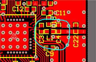
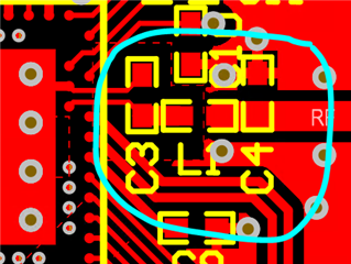
Your layout looks ok but some comments on the RF section:
This is a picture of the reference design. As you can see there is a specific way that the components are placed on the start of the RF section. 
It is recommended to include the full pi-network as it serves both as matching component for a 50 transmission line but also as a filter for the harmonics. I highly recommend that you copy the layout as exact as possible. So including the shunt cap after the series inductor is recommended.
I see that you are suing a Johanson Tech antenna but the components that you have selected does not seem to match the recommendation in the datasheet. Have you contacted the antenna manufacturer for guidance on the matching components?
Note: We do have some guides and references that might be of interest, there is also a reply from Kaja in this case where someone use the same antenna.
Regards,
Jonathan
Thank you so much for the review!
I don't mind it being public.
No I have not done any RF design before.
As for the component selection, I contacted Johanson Tech in order get more detailed documentation. I got my component values from this datasheet 2450AT42E010B.pdf and the exact components from this file 2450AT42E0100-EB1SMA_schematic.pdf.
So after adding the missing cap to complete the pi-network will my RF section be ok?
Best regards
Emil
Hi Emil,
Johanson Tech knows their antenna best, but al designs are a bit different so some tuning might be needed to achieve the best possible result. The same applies for the radio matching network also. So to get the best result one would tune the radio and than antenna.
But , yes looks fine to me if you include the full Pi-network and try to get the layout as close to the redesign as possible in that area. 
Just make sure that the transmission line is 50 Ohm and then it should be all good.
Feel free to send a updated design for confirmation or if there are any other questions.
Regards,
Jonathan
That's great to hear. Thanks again for your help!
Best regards
Emil