Hi,
I have several questions about the dongle board.
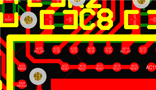
1. Why should the p0.19,20,..,25 be connected to the reset pin?
2. what is the difference between the reset button and disconnecting the power to enter the DFU mode?
I have downloaded the open bootloader code on the nrf52840 devkit. Then I have programmed the board with a blinky example. Once I switch off and then on the board, it enter the DFU mode, unlike the dongle running the app. Why?
3. If I want to power up the dongle with an external power through the vdd-nrf I should remove the SB2 and connect the SB1.
3.a. In this situation, can I program the dongle by using the USB port yet?
3.b. If I erased that through the link, how can I back to the DFU by using a USB port?