This post is older than 2 years and might not be relevant anymore
More Info: Consider searching for newer posts

Sample QSPI example Flash read giving 88 in read buffer

Hello developers,

I am currently using nRF52840 DK and want to integrate external flash in my already developed Open Thread based application. My idea is to store 200-300 sample data from sensor into external flash memory and send all data at specific interval from my end device in single payload via MQTT-SN. The MQTT-SN part is already developed and i am looking for help and guidance in the flash interface.

I started with peripheral example QSPI present in nrf5 SDK although without any success. The Erase, Read, Write process doesn't give error logs but it also doesn't read the data properly. It always give me 0x88 0x88 in the read buffer. Here are the logs of the following sample example:

<info> app: QSPI write and read example using 24bit addressing mode
<info> app: QSPI example started.
<info> app: Process of erasing first block start
<info> app: Process of writing data start
<info> app: Data read
<info> app: Compare...
<info> app: Data inconsistent
<info> app: QSPI write and read example using 24bit addressing mode
<info> app: QSPI example started.
<info> app: Process of erasing first block start
<info> app: Process of writing data start
<info> app: Data read
<info> app: Compare...
<info> app: Data inconsistent

I have checked my DK the jumpers as written in docs are soldered perfectly So this isn't a hardware issue. How should i run the sample QSPI example successfully.

So can anyone please help me ?

Parents
No Data
Reply
  • Hello,

    Thanks for quick reply.

    Has the example from the SDK been modified? If so, could you share exactly what you've modified?

    No the main.c file  is same as it is. I have just added the QSPI pin definition in sdk_config.h file, as it was showing QSPI_NO_PIN_Selected in sdk_config.

    I have added my main.c file and sdk_config file below.

    /**
     * Copyright (c) 2016 - 2020, Nordic Semiconductor ASA
     *
     * All rights reserved.
     *
     * Redistribution and use in source and binary forms, with or without modification,
     * are permitted provided that the following conditions are met:
     *
     * 1. Redistributions of source code must retain the above copyright notice, this
     *    list of conditions and the following disclaimer.
     *
     * 2. Redistributions in binary form, except as embedded into a Nordic
     *    Semiconductor ASA integrated circuit in a product or a software update for
     *    such product, must reproduce the above copyright notice, this list of
     *    conditions and the following disclaimer in the documentation and/or other
     *    materials provided with the distribution.
     *
     * 3. Neither the name of Nordic Semiconductor ASA nor the names of its
     *    contributors may be used to endorse or promote products derived from this
     *    software without specific prior written permission.
     *
     * 4. This software, with or without modification, must only be used with a
     *    Nordic Semiconductor ASA integrated circuit.
     *
     * 5. Any software provided in binary form under this license must not be reverse
     *    engineered, decompiled, modified and/or disassembled.
     *
     * THIS SOFTWARE IS PROVIDED BY NORDIC SEMICONDUCTOR ASA "AS IS" AND ANY EXPRESS
     * OR IMPLIED WARRANTIES, INCLUDING, BUT NOT LIMITED TO, THE IMPLIED WARRANTIES
     * OF MERCHANTABILITY, NONINFRINGEMENT, AND FITNESS FOR A PARTICULAR PURPOSE ARE
     * DISCLAIMED. IN NO EVENT SHALL NORDIC SEMICONDUCTOR ASA OR CONTRIBUTORS BE
     * LIABLE FOR ANY DIRECT, INDIRECT, INCIDENTAL, SPECIAL, EXEMPLARY, OR
     * CONSEQUENTIAL DAMAGES (INCLUDING, BUT NOT LIMITED TO, PROCUREMENT OF SUBSTITUTE
     * GOODS OR SERVICES; LOSS OF USE, DATA, OR PROFITS; OR BUSINESS INTERRUPTION)
     * HOWEVER CAUSED AND ON ANY THEORY OF LIABILITY, WHETHER IN CONTRACT, STRICT
     * LIABILITY, OR TORT (INCLUDING NEGLIGENCE OR OTHERWISE) ARISING IN ANY WAY OUT
     * OF THE USE OF THIS SOFTWARE, EVEN IF ADVISED OF THE POSSIBILITY OF SUCH DAMAGE.
     *
     */
    /** @file
     * @defgroup qspi_example_main main.c
     * @{
     * @ingroup qspi_example
     *
     * @brief QSPI Example Application main file.
     *
     * This file contains the source code for a sample application using QSPI.
     */
    
    #include <stdio.h>
    #include <string.h>
    #include <stdlib.h>
    #include "nrf_drv_qspi.h"
    #include "nrf_delay.h"
    #include "app_util_platform.h"
    #include "app_error.h"
    #include "boards.h"
    
    #include "nrf_log.h"
    #include "nrf_log_ctrl.h"
    #include "nrf_log_default_backends.h"
    #include "sdk_config.h"
    
    #define QSPI_STD_CMD_WRSR   0x01
    #define QSPI_STD_CMD_RSTEN  0x66
    #define QSPI_STD_CMD_RST    0x99
    
    #define QSPI_TEST_DATA_SIZE 256
    
    #define WAIT_FOR_PERIPH() do { \
            while (!m_finished) {} \
            m_finished = false;    \
        } while (0)
    
    static volatile bool m_finished = false;
    static uint8_t m_buffer_tx[QSPI_TEST_DATA_SIZE];
    static uint8_t m_buffer_rx[QSPI_TEST_DATA_SIZE];
    
    static void qspi_handler(nrf_drv_qspi_evt_t event, void * p_context)
    {
        UNUSED_PARAMETER(event);
        UNUSED_PARAMETER(p_context);
        m_finished = true;
    }
    
    static void configure_memory()
    {
        uint8_t temporary = 0x40;
        uint32_t err_code;
        nrf_qspi_cinstr_conf_t cinstr_cfg = {
            .opcode    = QSPI_STD_CMD_RSTEN,
            .length    = NRF_QSPI_CINSTR_LEN_1B,
            .io2_level = true,
            .io3_level = true,
            .wipwait   = true,
            .wren      = true
        };
    
        // Send reset enable
        err_code = nrf_drv_qspi_cinstr_xfer(&cinstr_cfg, NULL, NULL);
        APP_ERROR_CHECK(err_code);
    
        // Send reset command
        cinstr_cfg.opcode = QSPI_STD_CMD_RST;
        err_code = nrf_drv_qspi_cinstr_xfer(&cinstr_cfg, NULL, NULL);
        APP_ERROR_CHECK(err_code);
    
        // Switch to qspi mode
        cinstr_cfg.opcode = QSPI_STD_CMD_WRSR;
        cinstr_cfg.length = NRF_QSPI_CINSTR_LEN_2B;
        err_code = nrf_drv_qspi_cinstr_xfer(&cinstr_cfg, &temporary, NULL);
        APP_ERROR_CHECK(err_code);
    }
    
    
    int main(void)
    {
        uint32_t i;
        uint32_t err_code;
    
        err_code = NRF_LOG_INIT(NULL);
        APP_ERROR_CHECK(err_code);
    
        NRF_LOG_DEFAULT_BACKENDS_INIT();
    
        NRF_LOG_INFO(""
                     "QSPI write and read example using 24bit addressing mode");
    
        srand(0);
        for (i = 0; i < QSPI_TEST_DATA_SIZE; ++i)
        {
            m_buffer_tx[i] = (uint8_t)rand();
        }
    
        nrf_drv_qspi_config_t config = NRF_DRV_QSPI_DEFAULT_CONFIG;
    
        err_code = nrf_drv_qspi_init(&config, qspi_handler, NULL);
        APP_ERROR_CHECK(err_code);
        NRF_LOG_INFO("QSPI example started.");
    
        configure_memory();
    
        m_finished = false;
        err_code = nrf_drv_qspi_erase(NRF_QSPI_ERASE_LEN_64KB, 0);
        APP_ERROR_CHECK(err_code);
        WAIT_FOR_PERIPH();
        NRF_LOG_INFO("Process of erasing first block start");
    
        err_code = nrf_drv_qspi_write(m_buffer_tx, QSPI_TEST_DATA_SIZE, 0);
        APP_ERROR_CHECK(err_code);
        WAIT_FOR_PERIPH();
        NRF_LOG_INFO("Process of writing data start");
    
        err_code = nrf_drv_qspi_read(m_buffer_rx, QSPI_TEST_DATA_SIZE, 0);
        WAIT_FOR_PERIPH();
        NRF_LOG_INFO("Data read");
    
        NRF_LOG_INFO("Compare...");
        if (memcmp(m_buffer_tx, m_buffer_rx, QSPI_TEST_DATA_SIZE) == 0)
        {
            NRF_LOG_INFO("Data consistent");
        }
        else
        {
            NRF_LOG_INFO("Data inconsistent");
        }
    
        nrf_drv_qspi_uninit();
    
        for (;;)
        {
        }
    }
    
    /** @} */
    

    SDK_CONFIG file

    / <e> NRFX_QSPI_ENABLED - nrfx_qspi - QSPI peripheral driver
    //==========================================================
    #ifndef NRFX_QSPI_ENABLED
    #define NRFX_QSPI_ENABLED 1
    #endif
    // <o> NRFX_QSPI_CONFIG_SCK_DELAY - tSHSL, tWHSL and tSHWL in number of 16 MHz periods (62.5 ns).  <0-255> 
    
    
    #ifndef NRFX_QSPI_CONFIG_SCK_DELAY
    #define NRFX_QSPI_CONFIG_SCK_DELAY 1
    #endif
    
    // <o> NRFX_QSPI_CONFIG_XIP_OFFSET - Address offset in the external memory for Execute in Place operation. 
    #ifndef NRFX_QSPI_CONFIG_XIP_OFFSET
    #define NRFX_QSPI_CONFIG_XIP_OFFSET 0
    #endif
    
    // <o> NRFX_QSPI_CONFIG_READOC  - Number of data lines and opcode used for reading.
     
    // <0=> FastRead 
    // <1=> Read2O 
    // <2=> Read2IO 
    // <3=> Read4O 
    // <4=> Read4IO 
    
    #ifndef NRFX_QSPI_CONFIG_READOC
    #define NRFX_QSPI_CONFIG_READOC 0
    #endif
    
    // <o> NRFX_QSPI_CONFIG_WRITEOC  - Number of data lines and opcode used for writing.
     
    // <0=> PP 
    // <1=> PP2O 
    // <2=> PP4O 
    // <3=> PP4IO 
    
    #ifndef NRFX_QSPI_CONFIG_WRITEOC
    #define NRFX_QSPI_CONFIG_WRITEOC 0
    #endif
    
    // <o> NRFX_QSPI_CONFIG_ADDRMODE  - Addressing mode.
     
    // <0=> 24bit 
    // <1=> 32bit 
    
    #ifndef NRFX_QSPI_CONFIG_ADDRMODE
    #define NRFX_QSPI_CONFIG_ADDRMODE 0
    #endif
    
    // <o> NRFX_QSPI_CONFIG_MODE  - SPI mode.
     
    // <0=> Mode 0 
    // <1=> Mode 1 
    
    #ifndef NRFX_QSPI_CONFIG_MODE
    #define NRFX_QSPI_CONFIG_MODE 0
    #endif
    
    // <o> NRFX_QSPI_CONFIG_FREQUENCY  - Frequency divider.
     
    // <0=> 32MHz/1 
    // <1=> 32MHz/2 
    // <2=> 32MHz/3 
    // <3=> 32MHz/4 
    // <4=> 32MHz/5 
    // <5=> 32MHz/6 
    // <6=> 32MHz/7 
    // <7=> 32MHz/8 
    // <8=> 32MHz/9 
    // <9=> 32MHz/10 
    // <10=> 32MHz/11 
    // <11=> 32MHz/12 
    // <12=> 32MHz/13 
    // <13=> 32MHz/14 
    // <14=> 32MHz/15 
    // <15=> 32MHz/16 
    
    #ifndef NRFX_QSPI_CONFIG_FREQUENCY
    #define NRFX_QSPI_CONFIG_FREQUENCY 15
    #endif
    
    // <s> NRFX_QSPI_PIN_SCK - SCK pin value.
    #ifndef NRFX_QSPI_PIN_SCK
    #define NRFX_QSPI_PIN_SCK 19
    #endif
    
    // <s> NRFX_QSPI_PIN_CSN - CSN pin value.
    #ifndef NRFX_QSPI_PIN_CSN
    #define NRFX_QSPI_PIN_CSN 17
    #endif
    
    // <s> NRFX_QSPI_PIN_IO0 - IO0 pin value.
    #ifndef NRFX_QSPI_PIN_IO0
    #define NRFX_QSPI_PIN_IO0 20
    #endif
    
    // <s> NRFX_QSPI_PIN_IO1 - IO1 pin value.
    #ifndef NRFX_QSPI_PIN_IO1
    #define NRFX_QSPI_PIN_IO1 21
    #endif
    
    // <s> NRFX_QSPI_PIN_IO2 - IO2 pin value.
    #ifndef NRFX_QSPI_PIN_IO2
    #define NRFX_QSPI_PIN_IO2 22
    #endif
    
    // <s> NRFX_QSPI_PIN_IO3 - IO3 pin value.
    #ifndef NRFX_QSPI_PIN_IO3
    #define NRFX_QSPI_PIN_IO3 23
    #endif
    
    // <o> NRFX_QSPI_CONFIG_IRQ_PRIORITY  - Interrupt priority
     
    // <0=> 0 (highest) 
    // <1=> 1 
    // <2=> 2 
    // <3=> 3 
    // <4=> 4 
    // <5=> 5 
    // <6=> 6 
    // <7=> 7 
    
    #ifndef NRFX_QSPI_CONFIG_IRQ_PRIORITY
    #define NRFX_QSPI_CONFIG_IRQ_PRIORITY 6
    #endif
    
    // </e>


    // <e> QSPI_ENABLED - nrf_drv_qspi - QSPI peripheral driver - legacy layer
    //==========================================================
    #ifndef QSPI_ENABLED
    #define QSPI_ENABLED 1
    #endif
    // <o> QSPI_CONFIG_SCK_DELAY - tSHSL, tWHSL and tSHWL in number of 16 MHz periods (62.5 ns).  <0-255> 
    
    
    #ifndef QSPI_CONFIG_SCK_DELAY
    #define QSPI_CONFIG_SCK_DELAY 1
    #endif
    
    // <o> QSPI_CONFIG_XIP_OFFSET - Address offset in the external memory for Execute in Place operation. 
    #ifndef QSPI_CONFIG_XIP_OFFSET
    #define QSPI_CONFIG_XIP_OFFSET 0
    #endif
    
    // <o> QSPI_CONFIG_READOC  - Number of data lines and opcode used for reading.
     
    // <0=> FastRead 
    // <1=> Read2O 
    // <2=> Read2IO 
    // <3=> Read4O 
    // <4=> Read4IO 
    
    #ifndef QSPI_CONFIG_READOC
    #define QSPI_CONFIG_READOC 4
    #endif
    
    // <o> QSPI_CONFIG_WRITEOC  - Number of data lines and opcode used for writing.
     
    // <0=> PP 
    // <1=> PP2O 
    // <2=> PP4O 
    // <3=> PP4IO 
    
    #ifndef QSPI_CONFIG_WRITEOC
    #define QSPI_CONFIG_WRITEOC 3
    #endif
    
    // <o> QSPI_CONFIG_ADDRMODE  - Addressing mode.
     
    // <0=> 24bit 
    // <1=> 32bit 
    
    #ifndef QSPI_CONFIG_ADDRMODE
    #define QSPI_CONFIG_ADDRMODE 0
    #endif
    
    // <o> QSPI_CONFIG_MODE  - SPI mode.
     
    // <0=> Mode 0 
    // <1=> Mode 1 
    
    #ifndef QSPI_CONFIG_MODE
    #define QSPI_CONFIG_MODE 0
    #endif
    
    // <o> QSPI_CONFIG_FREQUENCY  - Frequency divider.
     
    // <0=> 32MHz/1 
    // <1=> 32MHz/2 
    // <2=> 32MHz/3 
    // <3=> 32MHz/4 
    // <4=> 32MHz/5 
    // <5=> 32MHz/6 
    // <6=> 32MHz/7 
    // <7=> 32MHz/8 
    // <8=> 32MHz/9 
    // <9=> 32MHz/10 
    // <10=> 32MHz/11 
    // <11=> 32MHz/12 
    // <12=> 32MHz/13 
    // <13=> 32MHz/14 
    // <14=> 32MHz/15 
    // <15=> 32MHz/16 
    
    #ifndef QSPI_CONFIG_FREQUENCY
    #define QSPI_CONFIG_FREQUENCY 1
    #endif
    
    // <s> QSPI_PIN_SCK - SCK pin value.
    #ifndef QSPI_PIN_SCK
    #define QSPI_PIN_SCK 19
    #endif
    
    // <s> QSPI_PIN_CSN - CSN pin value.
    #ifndef QSPI_PIN_CSN
    #define QSPI_PIN_CSN 17
    #endif
    
    // <s> QSPI_PIN_IO0 - IO0 pin value.
    #ifndef QSPI_PIN_IO0
    #define QSPI_PIN_IO0 20
    #endif
    
    // <s> QSPI_PIN_IO1 - IO1 pin value.
    #ifndef QSPI_PIN_IO1
    #define QSPI_PIN_IO1 21
    #endif
    
    // <s> QSPI_PIN_IO2 - IO2 pin value.
    #ifndef QSPI_PIN_IO2
    #define QSPI_PIN_IO2 22
    #endif
    
    // <s> QSPI_PIN_IO3 - IO3 pin value.
    #ifndef QSPI_PIN_IO3
    #define QSPI_PIN_IO3 23
    #endif
    
    // <o> QSPI_CONFIG_IRQ_PRIORITY  - Interrupt priority
     
    
    // <i> Priorities 0,2 (nRF51) and 0,1,4,5 (nRF52) are reserved for SoftDevice
    // <0=> 0 (highest) 
    // <1=> 1 
    // <2=> 2 
    // <3=> 3 
    // <4=> 4 
    // <5=> 5 
    // <6=> 6 
    // <7=> 7 
    
    #ifndef QSPI_CONFIG_IRQ_PRIORITY
    #define QSPI_CONFIG_IRQ_PRIORITY 6
    #endif
    
    // </e>
    

    Hardware Setup:

    The nRF52840 Dk board is connected with USB cable on port micro USB port (not nRF uSB). The nRF Power source is selected to VDD. And SW6 is selected to nRF only.  

    LogiC Analyzer:

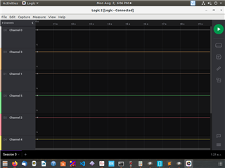
    I am not seeing any movement on Clock pin and CS pin as well in Logic analyzer.

    What could be the possible issue ? What step i can do next ?

Children
Related