
First of all i am using QSPI sample example from nRF5 SDK for Thread and Zigbee which indeed is based on nRF5 SDK 16.0. So i was looking to integrate external flash memory in my already developed thread application. So i started with simple sample QSPi example present in peripheral folder in SDK. The demo example itself doesn't work for me.
Whenever i read the data from memory it just gives 0x88 0x88 0x88 0x88 in the rx_buffer. Even after erasing the flash when i read the data it gives 0x88 only. In sdk_config.h file i can see that the QSPI pins are undefined. I have also tried setting the QSPI pins by referring the external memory docs in nrf52840 docs. Still the same issue of receiving 0x88 data.
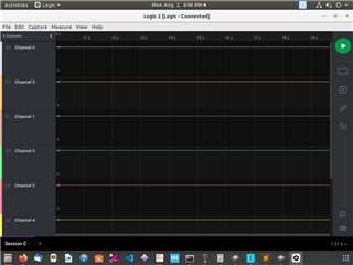
LOGIC ANALYZER
So than i connected Logic Analyzer on all the pins of External memory QSPI connection 17,19,20,21,22,23 and i don't see any movement on any pins. Even SCLK pins are not generating clock signals. So clock signals are also not getting generated.
Hardware Setup:
Currently giving power supply to nRF52840 kit from external power supply micro usb port (not nRF USB). nRF power source switch is set to VDD and the SW6 is set to nRF only mode.
What could be the possible issue here. Is there any QSPI example available with sdk_config file already configured. If yes, kindly attach in reply.
Waiting patiently again for someone reply.
