Hi,
I want to add some auto-test capability to my nRF5340-based project.
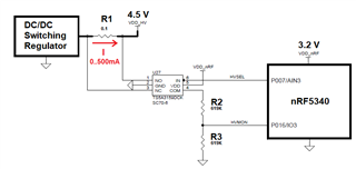
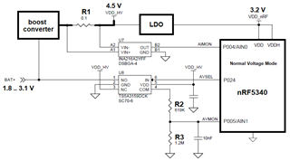
I thought one useful feature would be to measure voltage AND current at the hot node when all devices are active.
I needed a solution which uses few of nRF5340 pins, robust and cheap enough.
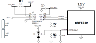
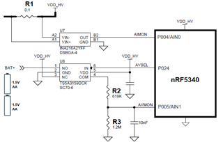
This circuit exploits one ADC channel (with 0.6V internal reference) and one GPIO.
step 1. Set HVSEL Low. Measure HVMON = V+
step 2. Set HVSEL High. Measure HVMON = V-
step 3. calculate current I = 2*(V+ - V-)/0.1
The resistors have guess values.
I'd appreciate any criticism and suggestions to improve it.


 I made your perplexities mine. I think this last step is more decent. Do you agree ?