This post is older than 2 years and might not be relevant anymore
More Info: Consider searching for newer posts

RSSI and TX power from nRF 52

Hi, we are trying to characterize RSSI and TX output power with nRF52-DK board.

We used a nRF52-DK (TX) and 2.4-GHz BLE antenna (chip-type, RX) was connected to spectrum analyzer to measure RSSI.

Firstly, we set DK board to output 0 dBm, and theoretically it should have shown -30 dBm, but we could get only -47 dBm.

Secondly, we set to +4 dBm, and RSSI increased by about 4 dB, so it seems like DK was working fine, but showing more than -15 dB from somewhere and we'd like to know where it came from.

We directly measured the TX output power using SWF connector and spectrum analyzer by following this guideline:

https://infocenter.nordicsemi.com/index.jsp?topic=%2Fug_nrf52832_dk%2FUG%2Fnrf52_DK%2Fhw_rf_meas.html

But again, we could only see -10 ~ -15 dBm when DK board was set to output 0 dBm.

Can I get some help on these issues? Thank you in advance.

  • Hi,

    I'm a bit unsure what you mean when your say:

    Firstly, we set DK board to output 0 dBm, and theoretically it should have shown -30 dBm, but we could get only -47 dBm.

     Do you set the DK to a constant carrier with 0 dBm? Then you should see  ~0 dBm.

    Have a look at out white paper RF measurements

    Best regards,
    Kaja

  • Hi Kaja,

    For that sentence, I was meaning RSSI measurement results, rather than TX output power.

    Can you please let me know more details about the setup for TX power measurement?

    I'm trying to measure the TX output power of nRF52832 by using advertising mode and the setup described in https://infocenter.nordicsemi.com/index.jsp?topic=%2Fug_nrf52832_dk%2FUG%2Fnrf52_DK%2Fhw_rf_meas.html.

    But it seems like we need to use a proper data pattern.

    So, can you please share the codes that can be used for TX power measurement?

    Also, I'd like to learn about the setup for impedance measurement (S11) during TX mode.

    It will be highly appreciated if I can get your urgent assistance. Thank you in advance.

  • Hi,

    Kaja said:
    Have a look at out white paper RF measurements

     You can use DTM, direct test mode or, the one recommended for this measurements, radio test example. 

    PATA said:
    Also, I'd like to learn about the setup for impedance measurement (S11) during TX mode.

     Then you would use a VNA to measure on the output, instead of a signal analyzer. 


    We offer to do free HW review of designs, RF measurements, tuning of the radio and antenna.
    To get this service, please create a private DevZone ticket, use the topic HW verification, and upload HW files, both schematic and layout. 

    Best regards,
    Kaja

  • Hi Kaja,

    Thank you for your help. I will try to use DTM and radio test.

    In the meantime, can you please let me know more details about impedance measurement?

    I'm using network analyzer (NA) and my target device is nRF52, but I'd like to know which nRF codes or program I need to run to test each impedance during TX mode and that during RX mode.

    Thank you,

  • Hi,

    we usually don't do much impedance measurements of the radio, as tuning the radio by measuring output power and harmonics are more efficient. But doing impedance measurements of the radio you need to measure from the radio matching network, towards the radio. 
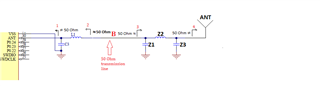
     From point B, looking towards the radio, point 2. The RF path towards the antenna, must be cut so that you don't get an extra load. 

    You can measure S22 if you put the radio in TX mode (constant, unmodulated carrier) and measure into the matching network, point 2. You should see an impedance closer to ~70 ohm because this gives the best operating conductions (less harmonics) for the PA. 

    Best regards,
    Kaja

Related