This post is older than 2 years and might not be relevant anymore
More Info: Consider searching for newer posts

Power profiling in nRF52832

Hi,

I am experimenting BLE nrf52832 to Ultra low power consumption during advertising , connection and transferring data  and also main thing is in ultra low power Mode.

I found

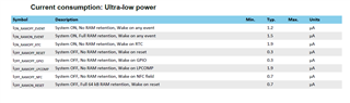
1. How to achieve SYSTEM_OFF, NO RAM retention, Wake on GPIO.  to achieve 0.3uA

2. PPK.

to test the BLE performance i choose nrf5 sdk 17.0.2 -> ble_template example . there i change after power cycle press button 4 to advertise ble.

for the process i choose nRF52832 DK with PPK 1 and PPK2 kit

with PPK1 kit

Power ON , standby mode -  5.21uA

Advertising                         -  62.64uA

after connected to mobile  -  24.04uA

sleep enter                        -  3.71uA

with PPK2 kit  - using AMP meter

Power ON , standby mode -  13.11uA

Advertising                         -  108.58uA

after connected to mobile  -  40.14uA

sleep enter                        -  11.27uA

with PPK2 kit with source meter

Power ON , standby mode -  547.21uA

Advertising                         -  615.64uA

after connected to mobile  -  303.97uA

sleep enter                        -  618.27uA

i don't know why this much difference for each kit and measuring type.

Here i attach my tested code

3730.ble_app_template.zip

Parents
  • Hi, the PCA10040 can be a bit tricky to measure current consumption correctly on.

    If the USB cable is plugged in and you are measuring through the current measurement header (PPK2 in ampere meter mode), you will see around 10 uA additional current in sleep. This is due to 1kHz noise from the USB interface. If you want to measure idle currents correctly on the current measurement header, unplug the USB cable, and power the DK with a stable supply on the External supply header.

    If you want to power the DK using PPK2 in SMU mode, you need to connect the positive lead to the current measurement header (closest to the debug out connector), and the negative lead on one of the GND connections. You will have to set the output voltage to match the DK VDD voltage exactly (should be around 2.7V) and this time you need to leave the USB cable plugged in to power the rest of the board.

    You can have a look at this blog: https://devzone.nordicsemi.com/nordic/cellular-iot-guides/b/hardware-design/posts/getting-started-with-current-measurements-on-the-nrf9160
    Even though it's written for the nRF91 DK, the two measurement methods shown in the picture are the same for the nRF52 DK.

    I would recommend using the PPK2, not the PPK1.

Reply
  • Hi, the PCA10040 can be a bit tricky to measure current consumption correctly on.

    If the USB cable is plugged in and you are measuring through the current measurement header (PPK2 in ampere meter mode), you will see around 10 uA additional current in sleep. This is due to 1kHz noise from the USB interface. If you want to measure idle currents correctly on the current measurement header, unplug the USB cable, and power the DK with a stable supply on the External supply header.

    If you want to power the DK using PPK2 in SMU mode, you need to connect the positive lead to the current measurement header (closest to the debug out connector), and the negative lead on one of the GND connections. You will have to set the output voltage to match the DK VDD voltage exactly (should be around 2.7V) and this time you need to leave the USB cable plugged in to power the rest of the board.

    You can have a look at this blog: https://devzone.nordicsemi.com/nordic/cellular-iot-guides/b/hardware-design/posts/getting-started-with-current-measurements-on-the-nrf9160
    Even though it's written for the nRF91 DK, the two measurement methods shown in the picture are the same for the nRF52 DK.

    I would recommend using the PPK2, not the PPK1.

Children
No Data
Related