
Hello.
I am working with an nrf52840 Development kit. My objective is to sample data from two ADC channels (the input signal has a maximum frequency of 10kHz) and send it via BLE to a tablet device. The graph is supposed to be shown on the display continuously.
I started with the ble_uart_app example. Configured two ADC channels:
Note that here >> SAMPLES_IN_BUFFER = 120;
void saadc_init(void)
{
    ret_code_t err_code;

    nrf_drv_saadc_config_t saadc_config = NRF_DRV_SAADC_DEFAULT_CONFIG;
    saadc_config.resolution = NRF_SAADC_RESOLUTION_8BIT;

    nrf_saadc_channel_config_t channel_0_config =
        NRF_DRV_SAADC_DEFAULT_CHANNEL_CONFIG_SE(NRF_SAADC_INPUT_AIN2);
    channel_0_config.gain = NRF_SAADC_GAIN1_4;
    channel_0_config.reference = NRF_SAADC_REFERENCE_VDD4;
    channel_0_config.acq_time = NRF_SAADC_ACQTIME_3US; //The value set for the timer must be higher than this value plus 2us (Conversion time) times the number of samples


    nrf_saadc_channel_config_t channel_1_config =
        NRF_DRV_SAADC_DEFAULT_CHANNEL_CONFIG_SE(NRF_SAADC_INPUT_AIN3);
    channel_1_config.gain = NRF_SAADC_GAIN1_4;
    channel_1_config.reference = NRF_SAADC_REFERENCE_VDD4;
    channel_1_config.acq_time = NRF_SAADC_ACQTIME_3US;


    err_code = nrf_drv_saadc_init(&saadc_config, saadc_callback);
    APP_ERROR_CHECK(err_code);

    err_code = nrf_drv_saadc_channel_init(0, &channel_0_config);
    APP_ERROR_CHECK(err_code);
    err_code = nrf_drv_saadc_channel_init(1, &channel_1_config);
    APP_ERROR_CHECK(err_code);

    err_code = nrf_drv_saadc_buffer_convert(adc_buf[0],SAMPLES_IN_BUFFER);
    APP_ERROR_CHECK(err_code);
    err_code = nrf_drv_saadc_buffer_convert(adc_buf[1],SAMPLES_IN_BUFFER);
    APP_ERROR_CHECK(err_code);
}
And configured the PPI for periodically triggering the ADC:
void saadc_sampling_event_init(void)
{
    ret_code_t err_code;

    err_code = nrf_drv_ppi_init();
    APP_ERROR_CHECK(err_code);

    nrf_drv_timer_config_t timer_cfg = NRF_DRV_TIMER_DEFAULT_CONFIG;
    timer_cfg.bit_width = NRF_TIMER_BIT_WIDTH_32;
    err_code = nrf_drv_timer_init(&TIMER_ADC, &timer_cfg, timer_handler);
    APP_ERROR_CHECK(err_code);

    /* setup m_timer for compare event every 400ms */
    uint32_t ticks = nrf_drv_timer_ms_to_ticks(&TIMER_ADC, 1);
    nrf_drv_timer_extended_compare(&TIMER_ADC,
                                   NRF_TIMER_CC_CHANNEL0,
                                   ticks,
                                   NRF_TIMER_SHORT_COMPARE0_CLEAR_MASK,
                                   false);
    nrf_drv_timer_enable(&TIMER_ADC);

    uint32_t timer_compare_event_addr = nrf_drv_timer_compare_event_address_get(&TIMER_ADC,
                                                                                NRF_TIMER_CC_CHANNEL0);
    uint32_t saadc_sample_task_addr   = nrf_drv_saadc_sample_task_get();

    /* setup ppi channel so that timer compare event is triggering sample task in SAADC */
    err_code = nrf_drv_ppi_channel_alloc(&m_ppi_channel);
    APP_ERROR_CHECK(err_code);

    err_code = nrf_drv_ppi_channel_assign(m_ppi_channel,
                                          timer_compare_event_addr,
                                          saadc_sample_task_addr);
    APP_ERROR_CHECK(err_code);
}
I understand from the datasheet that the time configured to trigger the ADC sampling (Ts) must obey the following rule:
Ts > (Acquisition time) + (Conversion time) (Section "Scan mode" in the SAADC specification at the datasheet)
I saw on the datasheet that the conversion time is less than 2 us (Found at the table "SAADC Electrical Specification" - Datasheet) :
and I know the acquisition time is configured at the ADC. From the code above, it can be seen that I configured it to an acquisition time of 3 us.
But since I am collecting 120 samples, I assume I must configure Ts as:
Ts > [ (Acquisition time) + (Conversion time) ]* 120 = 600 us.
So I configured PPI time as 1 ms because I thought it would provide a safety margin.
Referencing the ble_app_att_mtu_throughput I made a few changes aiming to increase the throughput of the BLE module.
I defined the MIN_CONN_INTERVAL and the MAX_CONN_INTERVAL as follows:
#define MIN_CONN_INTERVAL               MSEC_TO_UNITS(7.5, UNIT_1_25_MS)             /**< Minimum acceptable connection interval (20 ms), Connection interval uses 1.25 ms units. */
#define MAX_CONN_INTERVAL               MSEC_TO_UNITS(7.5, UNIT_1_25_MS)             /**< Maximum acceptable connection interval (75 ms), Connection interval uses 1.25 ms units. */
And I configured the sdk_config.h as follows:
// <i> Requested BLE GAP data length to be negotiated.

#ifndef NRF_SDH_BLE_GAP_DATA_LENGTH
#define NRF_SDH_BLE_GAP_DATA_LENGTH 251
#endif

// <o> NRF_SDH_BLE_PERIPHERAL_LINK_COUNT - Maximum number of peripheral links.
#ifndef NRF_SDH_BLE_PERIPHERAL_LINK_COUNT
#define NRF_SDH_BLE_PERIPHERAL_LINK_COUNT 1
#endif

// <o> NRF_SDH_BLE_CENTRAL_LINK_COUNT - Maximum number of central links.
#ifndef NRF_SDH_BLE_CENTRAL_LINK_COUNT
#define NRF_SDH_BLE_CENTRAL_LINK_COUNT 0
#endif

// <o> NRF_SDH_BLE_TOTAL_LINK_COUNT - Total link count.
// <i> Maximum number of total concurrent connections using the default configuration.

#ifndef NRF_SDH_BLE_TOTAL_LINK_COUNT
#define NRF_SDH_BLE_TOTAL_LINK_COUNT 1
#endif

// <o> NRF_SDH_BLE_GAP_EVENT_LENGTH - GAP event length.
// <i> The time set aside for this connection on every connection interval in 1.25 ms units.

#ifndef NRF_SDH_BLE_GAP_EVENT_LENGTH
#define NRF_SDH_BLE_GAP_EVENT_LENGTH 400
#endif

// <o> NRF_SDH_BLE_GATT_MAX_MTU_SIZE - Static maximum MTU size.
#ifndef NRF_SDH_BLE_GATT_MAX_MTU_SIZE
#define NRF_SDH_BLE_GATT_MAX_MTU_SIZE 247
#endif

// <o> NRF_SDH_BLE_GATTS_ATTR_TAB_SIZE - Attribute Table size in bytes. The size must be a multiple of 4.
#ifndef NRF_SDH_BLE_GATTS_ATTR_TAB_SIZE
#define NRF_SDH_BLE_GATTS_ATTR_TAB_SIZE 1408
#endif

// <o> NRF_SDH_BLE_VS_UUID_COUNT - The number of vendor-specific UUIDs.
#ifndef NRF_SDH_BLE_VS_UUID_COUNT
#define NRF_SDH_BLE_VS_UUID_COUNT 1
#endif
I also called the following functions:
void conn_evt_ext_enable(void){
    // Enable connection event extension
    ret_code_t err_code;
    ble_opt_t  opt;

    memset(&opt, 0x00, sizeof(opt));
    opt.common_opt.conn_evt_ext.enable = true;
    err_code = sd_ble_opt_set(BLE_COMMON_OPT_CONN_EVT_EXT, &opt);
    APP_ERROR_CHECK(err_code);
}

void data_len_set(uint8_t value)
{
    ret_code_t err_code;
    err_code = nrf_ble_gatt_data_length_set(&m_gatt, BLE_CONN_HANDLE_INVALID, value);
    APP_ERROR_CHECK(err_code);

    //m_test_params.data_len = value;
}
To allow connection event extension and to increase the data length. In the main() I call data_len_set(DATA_LENGTH_MAX);, where DATA_LENGTH_MAX = 251.
I am not sure if this is right, but to use maximum speed at the physical layer, I configured the BLE_CAP_EVT_PHY_UPDATE_REQUEST case in the ble_evt_handler() function as follows:
        case BLE_GAP_EVT_PHY_UPDATE_REQUEST:
        {
            NRF_LOG_DEBUG("PHY update request.");
            ble_gap_phys_t const phys =
            {
                .rx_phys = BLE_GAP_PHY_2MBPS,
                .tx_phys = BLE_GAP_PHY_2MBPS,
            };
            err_code = sd_ble_gap_phy_update(p_ble_evt->evt.gap_evt.conn_handle, &phys);
            APP_ERROR_CHECK(err_code);
        } break;
Now, the ADC callback saves sampled data at a queue:
void saadc_callback(nrf_drv_saadc_evt_t const * p_event)
{
    //char registerVal[41];

    //If there is data in the adc buffer and the ble is connected
    if ((p_event->type == NRF_DRV_SAADC_EVT_DONE))
    {
        ret_code_t err_code;

        err_code = nrf_drv_saadc_buffer_convert(p_event->data.done.p_buffer, SAMPLES_IN_BUFFER);
        APP_ERROR_CHECK(err_code);
        //SEGGER_RTT_WriteString(0, "SAADC_CALLBACK\n");

        if((!m_conn_handle) && (n_elements <= NUMBER_OF_PACKETS)){//Do this only if connected
              put_err_code = byte_queue_write(p_event->data.done.p_buffer, sizeof(adc_temp));//If data cannot be written to queue
              n_elements++;
        }
    }
}
This is how the queue was defined:
#define NUMBER_OF_PACKETS   450
NRF_QUEUE_DEF(uint16_t, m_byte_queue, SAMPLES_IN_BUFFER * NUMBER_OF_PACKETS * 2, NRF_QUEUE_MODE_NO_OVERFLOW);
NRF_QUEUE_INTERFACE_DEC(uint16_t, byte_queue);
NRF_QUEUE_INTERFACE_DEF(uint16_t, byte_queue, &m_byte_queue);
At the main loop, if there is data in the queue and the BLE is connected, I try to send the data.
    // Enter main loop.
    for (;;)
    {
        if((!m_conn_handle) && (n_elements > 10)){ //If it is connected and QUEUE is not empty
            get_err_code = byte_queue_read(adc_temp, sizeof(adc_temp)); // Reading from QUEUE
            saadc2ble_convert(adc_temp, adc_output);  //Convert the ADC data (16-bits) to BLE transfer data (8-bits)
            do{
                SEGGER_RTT_WriteString(0, "WAITING FOR A SUCCESSFUL BLE DATA SEND\n");
            }while(ble_nus_data_send(&m_nus, adc_output, &length, m_conn_handle));  //Sending data via BLE)
            n_elements--; //Countdown the element counter
            //Debugging message
            sprintf(error_string, "NUMBER OF ELEMENTS IN QUEUE: %d\n", n_elements);
            SEGGER_RTT_WriteString(0, error_string);
        }
    }
The saadc2ble_convert() function just converts the 16-bit data from the ADC sampling to 8-bit data to be transmitted via BLE.
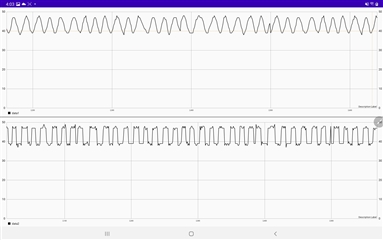
Finally, when I put this code to run with a square wave input to one channel and a sine wave input to another (Both with 600 Hz freq.) I get the following curve:
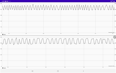
As I increase the frequency (2 kHz), the signal gets distorted:
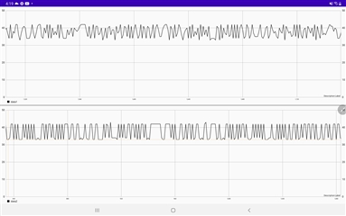
This is the signal seen on the screen of the tablet with an input of 10 kHz:
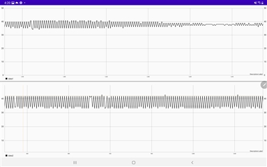
Interestingly, the signal also appears distorted with input at low frequencies. This is what I see when I set the frequency of the input signal at 20 Hz:
What I've been asked to do is: display the signal graph on the tablet screen. If any change happens at the input signal at the ADC, it should be reflected with a delay of less than one second on the tablet screen.
I've been working with this for a long time and the best results I got were what you can see in the 1st two images shown above. I've been listening to things like "I can hear music on my Bluetooth earphones. Why can't you make this work?". But from the little I know, BLE was not really developed for this kind of bulky and continuous data transfer.
So my first question is:
Can it be done using an nrf52840?
The second question comes in case the answer for the 1st is positive:
Is there any problem with how I configured the module? Can I still improve the throughput? Or the configuration is good and I am not correctly handling a Produce/Consumer problem?
I appreciate any help.
Thank you.

