This post is older than 2 years and might not be relevant anymore
More Info: Consider searching for newer posts

Trouble setting up for nRF52840 Dongle

I have a project I have been working on for a touch switch using the nRF52840. I have been developing it using NRF Connect 1.6.0 and testing it on the nRF52840DK board. It is working quite well now so I want to program a couple of dongles and run it in a real world test.

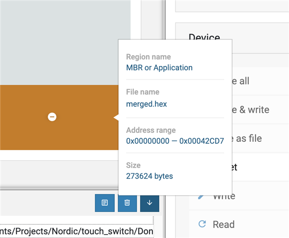
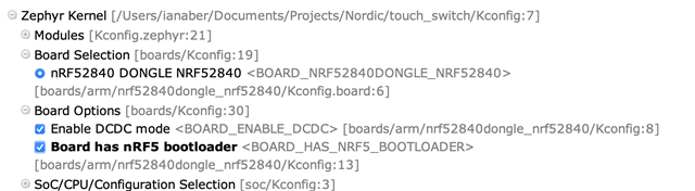
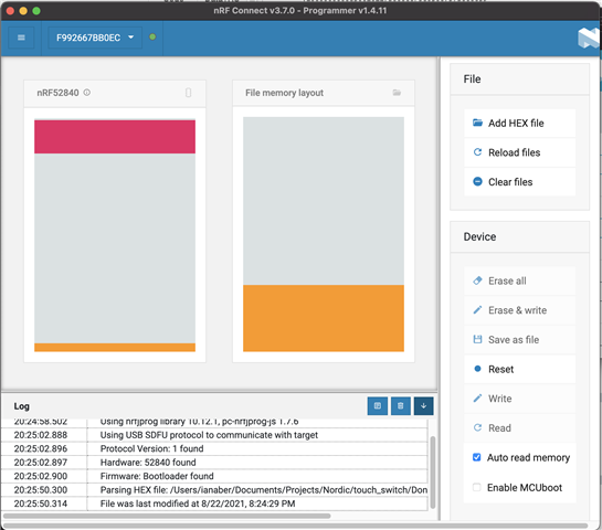
First of all I do not understand how to reconfigure my prject to use the dongle hardware. This was pretty easy using the nRF5 setups a year ago but it seems that the project configuration is set up at the start for a particular hardware device and cannot easily be changed. To circumvent this I created a new project and chose the nRF52840 Dongle as the board. I set all the required flags for peripherals etc and the program compiles and creates a Zephyr Merged hex file.My problem now is that I I drop that hex file into the programmer the write button stays disabled. It looks like the programmer does not see the memory configuration as valid yet the project configuration states that it should be linked for the boot loader.

What am I missing here? Is there some documentation that explains how to do what I am trying to do, i.e. take a project developed on the DK and program it for a dongle or some other hardware?

nRF5

Parents
  • Hi,

    What is the start address of the hex file you try to program? I ask because the Write button will be grayed out if the start address is lower than 0x1000. However, when you build for nrf52840dongle_nrf52840, the start address should automatically be 0x1000 (because FLASH_LOAD_OFFSET defaults to 0x1000 for that board). So, there must be some issue with your project. Did you by any chance specify CONFIG_FLASH_LOAD_OFFSET=0, overriding 0x1000?

  • I did not add anything to override the starting address. I just did a search for CONFIG_LOAD_FLASH in the whole project and the only references were in the generates files which all show it being set to 0x1000.

    I do not know how to read the hex file output to see what it is set to but the first few lines when view in Segger Embedded Studio are...

    :020000040000FA
    :1000000000830020217B00000F560300757B000059
    :10001000757B0000757B0000757B00000000000010
    :100020000000000000000000000000007D7A0000D9
    :10003000757B000000000000ED790000D571000024
    :10004000E17A00000D6D0300E17A0000E17A000022
    :10005000E17A0000E17A0000E17A0000E17A000034
    :10006000D56C0300E17A0000E17A0000F36C030034
    :10007000E17A0000E17A0000E17A0000E17A000014
    :10008000E17A0000E17A0000E17A0000E17A000004
    :10009000E17A0000E17A0000E17A0000E17A0000F4
    :1000A000E17A0000E17A0000E17A0000E17A0000E4
    :1000B000E17A0000E17A0000E17A0000E17A0000D4
    :1000C000E17A0000E17A0000E17A0000E17A0000C4
    :1000D000E17A0000E17A0000E17A0000E17A0000B4
    :1000E000E17A0000E17A0000E17A0000E17A0000A4
    :1000F000E17A0000E17A0000E17A0000E17A000094
    :100100007BB972B90029BEBF00204FF0004106E064

    Is there anything else I can share with you to make it easier to diagnose?
  • Hi,

    IanAber said:
    I did not add anything to override the starting address. I just did a search for CONFIG_LOAD_FLASH in the whole project and the only references were in the generates files which all show it being set to 0x1000.

    I see. Perhaps there is something else, but then I am not sure. You can see the start address of the hex file you added to nRF Connect Programming by hovering over it with the mouse in the File memory layout. It should be 0x1000. Is it?

  • As you surmised it appears to be set to 0 instead of 0x1000...

    How does this get set?

Reply Children
No Data
Related