This post is older than 2 years and might not be relevant anymore
More Info: Consider searching for newer posts

Basic schematic review request

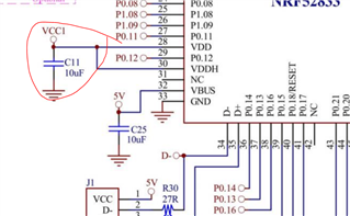
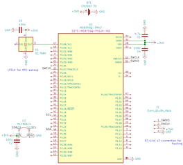
Looking for wisdom on wiring up the nRF (52833, via Raytac RF module). I'm having a hard time understanding (PS, Hardware Layout) section how the different power Configurations work. Ie for a battery-powered-only device, do I connect VDD and VDDH to the battery using bypass caps, and leave VBUS unconnected? (It's listed as having a higher min voltage than the battery provides). Do I need anything extra on the nRESET pin? (Bypass cap to ground?) On the example, it's going to a label off the schematic. I plan to flash via a ST-Link V2. Is that wiring above correct? Thank you.

Unrelated: What does *Standard drive, low frequency I/O only* mean on the pin listings. Ie, for TWIM (I2C) and SPI, should I avoid those pins? Thank you.

  • Hi,


    I'm having a hard time understanding (PS, Hardware Layout) section how the different power Configurations work. Ie for a battery-powered-only device, do I connect VDD and VDDH to the battery using bypass caps, and leave VBUS unconnected?

     It all depends on the voltage range the supply you're using is at. VDD and VDDH should be shorted together if the supply is between 1V7 and 3V6. This configuration is called Normal voltage mode, and only a 10 µF decoupling cap is needed for the module in this case:

    The VBUS interface has its own power supply, which means that this has to be supplied through VBUS with 5V if you're going to use the USB interface. If not, then you can just tie it to GND. 

    Do I need anything extra on the nRESET pin? (Bypass cap to ground?)

     No, the pin has an internal pullup that will be activated if the pin reset feature is activated by the fw. 

    I plan to flash via a ST-Link V2. Is that wiring above correct?

     Generally, the wiring is correct. I don't have any experience with ST-link, as we officially support SEGGER J-link. At least for the latter the wiring is correct. 

    What does *Standard drive, low frequency I/O only* mean on the pin listings. Ie, for TWIM (I2C) and SPI, should I avoid those pins?

     Some pins that are close to the radio are marked as standard drive, low frequency which means that any high frequency applications such as serial communication with these pins can affect the radio performance.  We there don't recommend using the pins for high frequency application.

    best regards
    Jared 

Related