Beware that this post is related to an SDK in maintenance mode
More Info: Consider nRF Connect SDK for new designs
This post is older than 2 years and might not be relevant anymore
More Info: Consider searching for newer posts

what are the required steps/files/definitions/commands to get RTT output from a custom app into RTT Viewer ?

I am using an nRF chip and the nRF SDK for 1st time and I think I am still at the steep part of the learning curve.

My problem is that I cannot get the log from my custom app in RTT Viewer. I use:

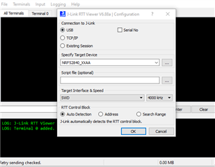
  • custom PCB with Taiyo Yuden EYSKBNZWB/nRF52840 Wireless Module
  • SDK 17.0.2
  • arm gcc 10.3.1
  • J-Link RTT Viewer V7.52b (JLinkRTTViewerExe)
  • nRF5_SDK/examples/peripheral/template_project

In my main.c source file I have included the following headers: https://infocenter.nordicsemi.com/index.jsp?topic=%2Fcom.nordic.infocenter.sdk5.v15.2.0%2Flib_nrf_log.html

  • #include "nrf_log_ctrl.h"
  • #include "nrf_log_default_backends.h"
  • #include "nrf_log.h"

Again in the main.c source file, I have the define - https://devzone.nordicsemi.com/f/nordic-q-a/29977/undefined-reference-to-nrf_log_default_backend_init

  • #define NRF_LOG_BACKEND_RTT_ENABLED 1

In the Makefile @ nRF5_SDK/examples/peripheral/template_project/pca10056/blank/armgcc I added the following line:

  • $(SDK_ROOT)/components/libraries/log/src/nrf_log_default_backends.c \

in order to solve the linker issue: main.c: undefined reference to `nrf_log_default_backends_init'

In the sdk_config.h file @ nRF5_SDK/examples/peripheral/template_project/pca10056/blank/config I have the follwoing settings:

The contents of my main.s source file are:

int main ( void ) {
    ret_code_t err_code = NRF_LOG_INIT ( NULL );
    APP_ERROR_CHECK ( err_code );
    NRF_LOG_DEFAULT_BACKENDS_INIT ();
    
    while ( true ) {
        uint32_t i ;

        for ( i = 0; i < 10; i++ ) {
            NRF_LOG_INFO ( "i = %u\r\n", i );
        }
    }
}

I thought that I could see some numbers printed in RTT VIewer but unfortunately I still can't manage to get the RTT output into the RTT Viewer after reading several posts so I would ask for help at this point. Any would be highly appreciated :-)

P.S. I think the connection PC <-> J-Link <-> PCB works fine as I managed to get an LED blink ca. every second.

Parents
  • Hi

    How is the connection to the J-Link set up in the RTT Viewer? 

    Also, in your sdk_config.h file, please make sure that the #define NRF_LOG_BACKEND_UART_ENABLED is set to 0. You can also try to set the NRF_FPRINTF_FLAG_AUTOMATIC_CR_ON_LF_ENABLED define back to 1 to see if that helps as well.

    Are you positive that the application runs as intended and actually enters this for loop printing values for you?

    Best regards,

    Simon

Reply
  • Hi

    How is the connection to the J-Link set up in the RTT Viewer? 

    Also, in your sdk_config.h file, please make sure that the #define NRF_LOG_BACKEND_UART_ENABLED is set to 0. You can also try to set the NRF_FPRINTF_FLAG_AUTOMATIC_CR_ON_LF_ENABLED define back to 1 to see if that helps as well.

    Are you positive that the application runs as intended and actually enters this for loop printing values for you?

    Best regards,

    Simon

Children
  • How is the connection to the J-Link set up in the RTT Viewer?

    - when I run the JLinkRTTViewer from the Terminal I use the following settings (tried also once with the S/N, but same issue, didn't expect to make any difference :-) :

    - when I press OK, I get the following output:

    in your sdk_config.h file, please make sure that the #define NRF_LOG_BACKEND_UART_ENABLED is set to 0.

    I do not have this macro name in my sdk_config.h file ! I read about it in several other posts, but it's just not present.

    I am talking about the sdk_config.h file located in /template_project/pca10056/blank/config/sdk_config.h

    There are some UART macros which, from the color codes in VScode, I guess are not supposed to be conditionally-compiled, e.g.:

    // <e> NRFX_UART_ENABLED - nrfx_uart - UART peripheral driver
    //==========================================================
    #ifndef NRFX_UART_ENABLED
    #define NRFX_UART_ENABLED 1
    #endif
    // <o> NRFX_UART0_ENABLED - Enable UART0 instance
    #ifndef NRFX_UART0_ENABLED
    #define NRFX_UART0_ENABLED 0
    #endif

    and there some others that, from the the color codes in VSCode again, are to be conditionally-compiled, e.g.

    // <e> UART_ENABLED - nrf_drv_uart - UART/UARTE peripheral driver - legacy layer
    //==========================================================
    #ifndef UART_ENABLED
    #define UART_ENABLED 1

    or this one

    // <e> UART0_ENABLED - Enable UART0 instance
    //==========================================================
    #ifndef UART0_ENABLED
    #define UART0_ENABLED 1
    #endif

    or this one

    // <e> UART1_ENABLED - Enable UART1 instance
    //==========================================================
    #ifndef UART1_ENABLED
    #define UART1_ENABLED 0
    #endif
    // </e>

    or this one

    // <e> APP_UART_ENABLED - app_uart - UART driver
    //==========================================================
    #ifndef APP_UART_ENABLED
    #define APP_UART_ENABLED 1
    #endif

    or these ones

    // <e> UART_CONFIG_LOG_ENABLED - Enables logging in the module.
    //==========================================================
    #ifndef UART_CONFIG_LOG_ENABLED
    #define UART_CONFIG_LOG_ENABLED 0
    #endif
    // <o> UART_CONFIG_LOG_LEVEL - Default Severity level
    // <0=> Off
    // <1=> Error
    // <2=> Warning
    // <3=> Info
    // <4=> Debug

    #ifndef UART_CONFIG_LOG_LEVEL
    #define UART_CONFIG_LOG_LEVEL 3
    #endif

    So, I do not have NRF_LOG_BACKEND_UART_ENABLED in my sdk_config.h file, but I do have some others whose states are variably either 1 or 0, but I do not know if any of those is meant to exactly correspond to the one you mentioned, i.e NRF_LOG_BACKEND_UART_ENABLED. So, my next question would be if one of those is a substitute for the one you mentioned, or NRF_LOG_BACKEND_UART_ENABLED is just somehow missing in the sdk_config.h file for the template project ?

    try to set the NRF_FPRINTF_FLAG_AUTOMATIC_CR_ON_LF_ENABLED define back to 1

    I just tried --> no change in the situation :-(

    The other thing as feedback: when I flash the program and RTT Viewer is not yet open, the J-Link LED looks as if it is in its heart beat mode. When I then open the RTT Viewer, the J-Link LED starts blinking quite fast, I guess it's the flickering mode, e.g. executing something ?! is it possible that some communication is going on, but I don't see the output ? When I then close the RTT Viewer, the J-Link LED shows steady light for ca. 7 seconds, then I guess its heart beat mode is initiated (as described in the User Manual for J-Link).

    Are you positive that the application runs as intended and actually enters this for loop printing values for you?

    No, I am not. To be honest I don't know how to make this sure. I am also currently trying to set up the debug configuration in VSCode using the launch.json file, but I have a problem there too, i.e.

    Checking target voltage...
    Target voltage: 3.30 V
    Listening on TCP/IP port 50000
    Connecting to target...
    Connected to target
    Waiting for GDB connection...Restoring target state and closing J-Link connection...
    Shutting down...
    SERVER CONSOLE DEBUG: onBackendConnect: gdb-server program closed
    GDB server exited. Waiting for next server to start...

    but I guess I'll need to open another ticket for this issue ...

  • Hi

    Sorry about the late reply. I've been out of office the past few days.

    Can you also explain how the module is connected to the debugging device?

    Indeed, the template project is very basic in regards to what is already added to it. Is there a reason you've chosen this example project? We generally recommend starting out with a larger project that's already implemented some of the features you'd already like to use. The peripheral_uart example for instance, uses the RTT backend for logging by default, so you could use that from scratch instead if that's of interest.

    Best regards,

    Simon

  • Hi, Simon,

    no issue about the delay, thanks for your new reply.

    In the meantime, I somehow managed to get the Debugging in VSCode running via OpenOCD. So, with regard to your last question from your previous reply:

    Are you positive that the application runs as intended and actually enters this for loop printing values for you?

    I removed the printing loop, and only inserted few NRF_LOG_INFO() lines before switching on an indicator LED to make sure the execution reaches there:

    // #includes ...
    // #defines ...
    
    int main ( void ) {
        nrf_gpio_cfg_output ( LED_PIN ) ;
        
        ret_code_t err_code = NRF_LOG_INIT ( NULL );
        APP_ERROR_CHECK ( err_code );
        
        NRF_LOG_DEFAULT_BACKENDS_INIT ();
        
        NRF_LOG_INFO ( "1r\n" );
        NRF_LOG_INFO ( "2\r\n" );
        NRF_LOG_INFO ( "3\r\n" );
        NRF_LOG_INFO ( "4\r\n" );
        NRF_LOG_INFO ( "5\r\n" );
        
        nrf_gpio_pin_set ( LED_PIN );   // LED switches on => execution reaches this line ?
    }

    LED switches on => execution does not break before it. I also stepped the code through in a Debugging session and could step over each NRF_LOG_INFO() call and then finally reached the LED-switch-on code. So, I assume the NRF_LOG_INFO() calls get executed, however no numbers get printed in the RTT Viewer.

    I also tried using the JLinkExe together with JLinkRTTClient as described in here:

    https://www.justinmklam.com/posts/2019/04/vscode-nrf52/

    but still nothing gets printed as with JLinkRTTViewer.

    With regard to the connection PCB <--> J-Link, from what I could measure with the multi-meter and by visually inspecting which cable goes where (not everything is visible under the silicon or epoxy or whatever has been applied there + I am kind of only firmware guy with basic hardware skills :-), it must be something like:

    https://imgur.com/L7qi8Oa

    Is there a reason you've chosen this example project?

    Well, currently I have no dev board to experiment with, but only an example device. So, my tasks were:

    • 1st task: make an LED blink (done);
    • 2nd task: get the logs working via RTT (stuck);
    • 3rd task: get readings from the device joystick and get those printed.

    So, I am stuck on the 2nd task :-) hence, I can't continue the plan :-(. I received the whole project, and probably by running it I might get RTT output, but if I get it, then I still won't have understood what is going on and required for RTT to work, which I find kind of annoying, because later it might lead to some bug when I do something else. So, the reason to use the very basic template project was just to get started clean, and add functionalities one-by-one when all has worked as expected - I think that is the more decent approach to getting to know something new, as is an nRF52 to me at the present moment.

    I will try the UART example as you suggest, but I will be happy to resolve my issue and understand also why it doesn't work and what exactly was missing and required for it to work.

    Greets

    Mario

Related